
Summary of Contents for PCI Digitizers ATS860
- Page 1 ATS860 User Manual 8 Bit, 250 MS/s Waveform Digitizer for PCI Bus Written for Hardware Version 1.0 July 2006 Edition Part Number: 860-USR-1...
- Page 3 Kirkland, Quebec Canada H9H 3C4 Telephone: (514) 633-0001 Fax: (514) 633-0021 E-mail: info@alazartech.com Web site: www.alazartech.com To comment on the documentation for ATS860, send e-mail to support@alazartech.com. Information required when contacting AlazarTech for technical support: Owned by: ___________________________ Serial Number:...
- Page 4 Important Information Warranty The ATS860 is warranted against defects in materials and workmanship for a period of one year from the date of shipment, as evidenced by receipts or other documentation. AlazarTech, Inc. will, at its option, repair or replace equipment that proves to be defective during the warranty period.
- Page 5 ULTIMATELY RESPONSIBLE FOR VERIFYING AND VALIDATING THE SUITABILITY OF ALAZARTECH INC. PRODUCTS WHENEVER ALAZARTECH, INC. PRODUCTS ARE INCORPORATED IN A SYSTEM OR APPLICATION, INCLUDING, WITHOUT LIMITATION, THE APPROPRIATE DESIGN, PROCESS AND SAFETY LEVEL OF SUCH SYSTEM OR APPLICATION. ATS860 User Manual...
- Page 6 Canadian Department of Communications This Class A digital apparatus meets all requirements of the Canadian Interference- Causing Equipment Regulations. Cet appareil numérique de la classe A respecte toutes les exigences du Règlement sur le matériel brouilleur du Canada. ATS860 User Manual...
- Page 7 Certain exemptions may apply in the USA, see FCC Rules §15.103 Exempted devices, and §15.105(c). Also available in sections of CFR 47. The CE Mark Declaration of Conformity will contain important supplementary information and instructions for the user or installer. ATS860 User Manual...
-
Page 8: Table Of Contents
Table of Contents CHAPTER 1 - INTRODUCTION ..........1 About Your ATS860 ..............2 Acquiring Data with Your ATS860..........3 Interactively Controlling your ATS860 with API Panel....4 ATS-SDK API ................5 ATS-VI LabVIEW VI..............5 ATS-Linux for ATS860..............6 Optional Upgrades ...............7 CHAPTER 2 - INSTALLATION AND CONFIGURATION...8 What You Need to Get Started ............9... - Page 9 AutoDMA for PRF Captures........... 55 Continuous Data Capture Using Dual Port Memory....56 CHAPTER 4 – USING API PANEL SOFTWARE..... 57 APPENDIX A - SPECIFICATIONS ........... 66 ATS860 User Manual...
-
Page 11: Chapter 1 - Introduction
Chapter 1 - Introduction This chapter describes the ATS860 and lists additional equipment. ATS860 User Manual... -
Page 12: About Your Ats860
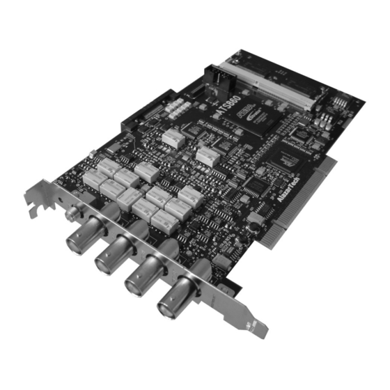
About Your ATS860 Thank you for your purchase of an ATS860. The ATS860 PCI based waveform digitizer has the following features: • Two 8-bit resolution analog input channels • Real-time sampling rate of 250 MS/s to 1 KS/s • 16 Million samples of onboard memory per channel, standard •... -
Page 13: Acquiring Data With Your Ats860
You can acquire data either programmatically by writing an application for your ATS860 or interactively with the API Panel software. If you want to integrate the ATS860 in your test and measurement or embedded OEM application, you can program the digitizer using C/C++, Visual BASIC or LabVIEW for Win32 (Windows 98SE, Windows 2000 and Windows XP) operating systems or C for Linux operating systems. -
Page 14: Interactively Controlling Your Ats860 With Api Panel
Interactively Controlling your ATS860 with API Panel The API Panel Soft Front Panel allows you to interactively control your ATS860 as you would a desktop oscilloscope. To launch the Scope Soft Front Panel, select Start » Programs » AlazarTech » API Panel The following screen will be displayed. -
Page 15: Ats-Sdk Api
ATS-SDK API The ATS-SDK API is used for programming the ATS860 in C/C++ or Visual BASIC. It provides the exact same API that is used for writing API Panel software. To help you get started, ATS-SDK comes with examples you can use or modify. -
Page 16: Ats-Linux For Ats860
ATS-Linux for ATS860 The ATS-Linux for ATS860 can be used for programming the ATS860 under Linux operating system. A binary driver is supplied that has been compiled for Kernel 2.6 running on an i386 platform. Sample program is supplied in C. The API is identical to the Windows API. -
Page 17: Optional Upgrades
ATS860: Dual Port Memory Upgrade • ATS860: External Clock Upgrade • ATS860: Trigger Output Upgrade • ATS860: Master/Slave SyncBoard 2 position • ATS860: Master/Slave SyncBoard 4 position • ATS860: Master/Slave SyncBoard 8 position • ATS860: 8M to 128M Memory Upgrade ATS860 User Manual... -
Page 18: Chapter 2 - Installation And Configuration
Chapter 2 - Installation and Configuration This chapter describes how to unpack, install, and configure your ATS860. ATS860 User Manual... -
Page 19: What You Need To Get Started
What You Need to Get Started To set up and use your ATS860, you will need the following: • One or more ATS860 digitizers • ATS860 Install Disk • For Master/Slave operation only: SyncBoard of appropriate width SyncBoard 2X for up to 2 digitizers... - Page 20 SyncBoard 4X for up to 4 digitizers SyncBoard 8X for up to 8 digitizers ATS860 User Manual...
-
Page 21: Unpacking
Notify AlazarTech if the digitizer appears damaged in any way. Do not install a damaged digitizer into your computer. • Never touch the exposed pins of the connectors. ATS860 User Manual... -
Page 22: Installing The Ats860
There are four main steps involved in installation: 1. Physically install the digitizer(s) and SyncBoard, if any, in your computer 2. Install ATS860 software driver, when prompted by the operating system 3. Install API Panel software that allows you to setup... - Page 23 1. Physically install the digitizer in your computer Make sure that your computer is powered off before you attempt to insert the ATS860 digitizer in one of the free PCI slots. For best noise performance, leave as much room as possible between your ATS860 and other hardware.
- Page 24 For Master/Slave Installation If you are installing multiple ATS860 digitizers that will be configured as a Master/Slave system, make sure that you insert all cards in adjacent slots. The connector on the SyncBoard that is labeled as “M” (Master), must be inserted into the Master/Slave connector of the left-most digitizer, if you are facing the BNC connectors of the ATS860 digitizers.
- Page 25 SyncBoard, the unused SyncBoard connectors must be on the right- hand side of the digitizers, if you are facing the BNC connectors of the ATS860 digitizers. Once you have completed this step, you should power the computer on.
- Page 26 2. Install ATS860 software driver, when prompted The following instructions guide you through the process of installing the ATS860 in a computer running Windows XP, Windows 2000 or Windows 98SE operating systems. Other operating systems, such as Windows NT, are not covered here.
- Page 27 Installing ATS860 Driver In Windows 98SE When you first plug in an ATS860 digitizer into a computer, the plug-n-play Windows 98SE operating system will detect the presence of a new PCI card and ask you to provide the device driver.
- Page 28 Operating system will display the Select a Device Driver dialog box again. Make sure the AlazarTech ATS860 PCI Digitizer is selected. Then click Next. g) Operating system will display the Update Driver Warning. This warning is meant to tell you that Windows does not recognize the hardware.
- Page 29 Typically, you should be the Administrator for the computer you are installing device drivers on. When you first plug in an ATS860 digitizer into a computer, the plug-n-play Windows 2000 operating system will detect the presence of a new PCI card and ask you to provide the device driver.
- Page 30 Operating system will display the Select a Device Driver dialog box again. Make sure the AlazarTech ATS860 PCI Digitizer is selected. Then click Next. h) Operating system will display the Update Driver Warning. This warning is meant to tell you that Windows does not recognize the hardware.
- Page 31 Typically, you should be the Administrator for the computer you are installing device drivers on. When you first plug in an ATS860 digitizer into a computer, the plug-n-play Windows XP operating system will detect the presence of a new PCI card and ask you to provide the device driver.
- Page 32 Make sure the path points to D:\, or wherever the ATS860.INF file resides. If you are using a floppy disk or a CD, make sure the disk is inserted in the drive. Click OK. Operating system will display the Select the device driver you want to install for this hardware dialog box again.
- Page 33 • Insert the ATS860 Install disk • Use Windows Explorer to navigate to the API Panel folder on the ATS860 Install Disk. Run Setup.exe program • Follow the instructions on the screen. If you are installing API Panel after having...
- Page 34 If, for any reason, installation does not start automatically, run the SETUP.EXE program. Follow the instructions on the screen. Note that you must have already installed the ATS860 drivers for any of the sample programs included with the ATS-SDK or ATS-VI to work properly. ATS860 User Manual...
-
Page 35: Installing The Ats860 In A Linux System
Installing the ATS860 in a Linux System ATS860 is fully compatible with the popular Linux operating system. AlazarTech supplies binary Linux drivers that have been compiled for Fedora Core 4 (kernel 2.6). Customers who require drivers for another version of Linux must contact the factory to obtain source code for the drivers (requires a Non-Disclosure Agreement). -
Page 36: Compiling The Ats860 Linux Driver
Compiling the ATS860 Linux Driver If you need to compile the ATS860 driver for a version of Linux other than Fedora Core 4, follow the following steps: 1. Install the Linux kernel header files. 2. Extract the driver sources using the command "tar xvfz PlxLinux-2006.01.10.tgz". -
Page 37: Configuring Internet Security And Virus Protection Software To Allow Proper Operation Of Ats Class Digitizers
PCI devices that have not been assigned to a software application by the user. Users of AlazarTech PCI digitizers must configure their security software to allow access to the PCI digitizers. - Page 38 Make sure AlazarTech hardware and software are fully functional • Re-install Norton Anti-Virus software AlazarTech PCI digitizer products are fully compatible with all internet security and anti-virus software. Users must make sure that their security software has been updated and configured properly. ATS860 User Manual...
-
Page 39: Updating Ats860 Driver
These updates may be required for product enhancements or for bug fixes. This section of the manual takes you through the steps required to update the device driver for the ATS860 PCI digitizer. In other words, this section shows you how to install a newer version of the driver, when you already have a previous version of the driver installed on your machine. - Page 40 9. To complete the installation, follow the instructions provided in the section labeled: a. Installing ATS860 Driver in Windows 98SE b. Installing ATS860 Driver in Windows 2000 c. Installing ATS860 Driver in Windows XP ATS860 User Manual...
-
Page 41: Chapter 3 - Hardware Overview
Chapter 3 - Hardware Overview This chapter includes an overview of the ATS860, explains the operation of each functional unit making up your ATS860, and describes the signal connections. Following is a high- level block diagram of ATS860. CH A... -
Page 42: Input Connectors
Input Connectors These ATS860 digitizers have one SMA connector for ECLK (External Clock) Input, two standard BNC female connectors for CH A and CH B analog input connections, one standard BNC female connector for the TRIG IN (External Trigger) input and one standard BNC female connector for TRIG OUT output. -
Page 43: Signal Connections
Use the EXT input for an external analog trigger only; data on the TRIG channel cannot be digitized. If External Clock Upgrade is installed on your ATS860, use the ECLK input for clocking the ATS860 in applications that require an external clock. Note that you must select the... -
Page 44: Analog Input
For accurate measurements, make sure the signal being measured is referenced to the same ground as your ATS860 by attaching the probe’s ground clip to the signal ground. The EXTernal Trigger input (labeled TRIG IN) has a programmable input range of ±5 V or ±1 V. -
Page 45: Pipelined Adc
Pipelined ADC Each of the two ADCs on the ATS860 is a pipelined flash converter with a maximum conversion rate of 250 MS/s. If you use an external clock, you must provide a free-running clock to ensure reliable operation. You also must follow all the timing specifications on the external clock as described in Appendix A, Specifications. -
Page 46: Specifying Pretrigger Depth
Specifying Pretrigger Depth ATS860 acquires a certain number of samples, called the pretrigger depth, before it allows the trigger circuitry to operate, thereby guaranteeing that the required number of sample points will be captured before trigger occurs. User is allowed to set pretrigger depth for an acquisition session. -
Page 47: Amplifier Bypass Option
ATS860 hardware includes the capability to bypass the input amplifier in order to maximize dynamic performance. ATS860 allows the user to set and reset the Amplifier Bypass Option using on-board DIP switches. The user can bypass the amplifier on any one, or both, channels of ATS860. - Page 48 ADC. It is very important that the user set both the “Near Switch” and “Far Switch” with the same settings. Failure to do so can cause measurement errors. ATS860 User Manual...
- Page 49 The default setting of all four of the DIP switches is shown below: The black square represents the plastic tab for the switch. Note that the actual tab may not be black. It may, in fact, be white. ATS860 User Manual...
- Page 50 Near and Far switches for that particular channel to be the same as the factory-set default: NOTE THAT ANY SETTINGS OTHER THAN THE ONES SHOWN ABOVE ARE ILLEGAL, AND MAY CAUSE DAMAGE TO THE ATS860 ANALOG CIRCUITRY ATS860 User Manual...
-
Page 51: Calibration
Externally recalibrate the ATS860 when this calibration interval has expired. This requires three very simple steps: 1. Verify whether or not ATS860 is still within its specifications. If it is, then your calibration can be extended by another one-year period 2. -
Page 52: Master/Slave Operation
Master/Slave Operation You can use two or more ATS860 digitizers in one system to increase the number of channels for your application by synchronizing digitizers using the appropriate SyncBoard. Currently, up to 16 channel (8 board) systems are supported for ATS860. For higher channel counts, contact the factory for special system configuration. -
Page 53: Restrictions
Good Installation Bad Installation • You must connect the appropriate SyncBoard to all of the ATS860 digitizers in your system. Note that all SyncBoards are polarized, so you cannot make a mistake in inserting them • If you are using fewer than the maximum number of digitizers allowed by the SyncBoard, make sure that the connector labeled “M”... - Page 54 The presence of a SyncBoard is detected by the ATS860 driver when the ATSApi DLL is loaded. This DLL gets loaded when you run any application program written for ATS860. Examples of such application programs are API Panel, one of the sample programs supplied with ATS-SDK or ATS-VI or any custom software written using ATS-SDK or ATS-VI.
-
Page 55: Hyperdisp Display Technology
® HyperDisP is a proprietary hardware technology contained in the ATS860 that reduces large datasets to a more manageable size, without losing any of the information contained in the signal. ® In other words, HyperDisP enables fast screen updates not by simply “skipping”... -
Page 56: Optional External Clock
Optional External Clock ATS860 PCI Digitizer optionally allows you to supply the ADC clock. This option is extremely important in many RF applications in which phase measurements must be made between the inputs themselves or between the inputs and an external event. -
Page 57: Slow External Clock
As such, there will be a timing error of 0 to 4 nanoseconds. For low bandwidth signals, this error can be considered to be negligible. Note that if you use Slow External Clock and your clock frequency is higher than 50 MHz, you may see significant signal distortion. ATS860 User Manual... -
Page 58: Selecting External Clock Impedance And Coupling For Hardware Version 1.2
For Hardware version 1.2 The input impedance and coupling of the External Clock input is DIP Switch selectable on the ATS860. A 4-pin (2 position) DIP switch, located on the secondary side in the top-right corner of the board, allows you to select between AC and DC coupling and 50Ω... - Page 59 Switch 1 is set. Therefore, input coupling is DC If Switch 2 is set, External Clock input impedance is 50 Ω. Otherwise, it is approximately 10 KΩ. Switch 2 is set. Therefore, input impedance is 50 Ω ATS860 User Manual...
- Page 60 Here are the possible settings for this DIP switch: AC Coupling 10KΩ impedance AC Coupling 50Ω impedance DC Coupling 10KΩ impedance DC Coupling 50Ω impedance ATS860 User Manual...
- Page 61 In general, it is advisable to use 10 KΩ input impedance for Slow External Clock, as the input in this mode is a TTL gate. If you have a strong enough TTL driver in the output stage of the clock generator, you can choose 50Ω impedance ATS860 User Manual...
-
Page 62: Optional Dual-Port Memory & Autodma
Optional Dual-Port Memory & AutoDMA One of the most unique features of the ATS860 is its optional dual-port memory and the associated AutoDMA mechanism of transferring data to host PC memory without any appreciable “in-process” software involvement. These features are particularly useful for applications that... -
Page 63: Real-Time Operating Systems
As such, the claim that an RTOS can remove all timing uncertainties in PRF application is suspect, to say the least. Furthermore, you may not be able to get software drivers for the selected RTOS for all the hardware components you need for your system. ATS860 User Manual... -
Page 64: Dual Port Memory
PRF. Note that the operating system overheads are part of this delay ATS860 solves this problem by providing optional dual-port memory. When operated in Multiple Record mode (Record Count > 1), a new record is being captured even while you read the previous one from the on-board memory. -
Page 65: Autodma For Prf Captures
ATS860’s proprietary AutoDMA feature allows the acquisition system to be re-armed by a hardware command and data transfer to be initiated by the hardware itself, thus removing virtually all “in-process”... -
Page 66: Continuous Data Capture Using Dual Port Memory
Continuous Data Capture Using Dual Port Memory ATS860, updated for Dual Port Memory, can also do continuous data capture to PC memory at typical rates up to 10 MS/s on two channels. Note that due to diverse nature of PCs and motherboards in the market, AlazarTech cannot guarantee proper operation of this mode in all PCs at this time. -
Page 67: Chapter 4 - Using Api Panel Software
Chapter 4 – Using API Panel Software This chapter provides a Quick Start Guide to the API Panel software supplied with your ATS860. API Panel Installation For installing API Panel software, refer to the installation section of this manual. Launching API Panel You can launch API Panel by the following two methods: 1. - Page 68 API Panel screen is divided into five sections: 1. Data Display Area 2. Hardware Control Area 3. Display Control Area 4. Information Area 5. Menu Area Information Area Data Display Area Menu Area Display Control Area Hardware Control Area ATS860 User Manual...
- Page 69 Hardware Control Area provides the user complete control over the hardware parameters of the ATS860. API Panel also performs complete error checking on all user selections to make sure that only valid settings are passed on to the hardware.
- Page 70 Trigger Control API Panel supports the dual-engine triggering featured on the ATS860. These trigger engines are called Engine X and Engine Y. For each engine, the user can select a trigger source, a trigger level and the trigger slope. User is allowed to set the same source on both engines for Windowed triggering applications.
- Page 71 No software triggers are generated. Once the required number of trigger events has occurred, data is displayed and the ATS860 is re-armed to capture data again. This mode is usually employed for capturing transient signals that occur repeatedly.
- Page 72 1000 or (128,000,000 / (Record Length + 16)) for the 128M model If any settings are found to be illegal, an error message is generated and the user is asked to enter the selections again. ATS860 User Manual...
- Page 73 The 40-bit timestamp is displayed as a 40-bit hexadecimal number. Each count of the timestamp corresponds to 2 sample clocks. This count is initialized to zero when the software instructs the ATS860 to start acquiring data and start looking for a trigger. ATS860 User Manual...
- Page 74 By expanding any System, users can check how many digitizers are included in the system and whether they are ATS860 or another type of digitizer. Users can also expand each digitizer to see how many input channels that digitizer provides.
- Page 75 A “Find Trigger” command is also provided to make it easy to scroll back to the trigger point. Help menu allows the user to check which version of API Panel, ATS860 driver and SDK are being used. This feature is very useful for technical support. ATS860 User Manual...
-
Page 76: Appendix A - Specifications
Appendix A - Specifications This appendix lists the specifications of the ATS860. These specifications are typical at 25 °C unless otherwise stated. The operating temperature range is 0 to 50 °C. System Requirements Pentium based computer with at least one free PCI slot, 256 MB RAM, 40 MB of free hard disk space, SVGA display adaptor and monitor with at least an 800 x 600 resolution. - Page 77 Yes, independently for each channel Input Range Approximately TBD mV rms Input Coupling DC, irrespective of input coupling setting for the channel 50 Ω, irrespective of input impedance setting Input Impedance for the channel Input Bandwidth (-3dB) 100 MHz ATS860 User Manual...
- Page 78 Internal Clock accuracy ±25 ppm Dynamic Parameters Typical values measured using a randomly selected ATS860 with Amplifier Bypass Mode. Input was provided by a HP8656A signal generator, followed by a 9-pole, 1 MHz band-pass filter (TTE Q36T-1M-100K-50-720B). Input frequency was set at 1 MHz and output amplitude was 500 mV rms, which is approximately 95% of the 525 mVrms full scale input in Amplifier Bypass Mode.
- Page 79 Software selectable with a 10 us resolution. Maximum settable value is 3,600 seconds. Can also be disabled to wait indefinitely for a trigger event TRIG OUT Output Connector AUX I/O Output Signal 5 Volt TTL Synchronization Synchronized to rising edge of sampling clock ATS860 User Manual...
- Page 80 ±28V (DC + peak AC without external attenuation) Coupling AC or DC, software selectable Certification and Compliances CE Mark Compliance Materials Supplied One ATS860 Digitizer One ATS860 Install Disk (CD) One ATS860 User Manual All specifications are subject to change without notice ATS860 User Manual...
- Page 82 ALAZAR TECHNOLOGIES INC. 3551 St-Charles, Unit 640 Kirkland, QC CANADA H9H 3C4 Tel: (514) 633-0001 Fax: (514) 633-0021 E-mail: info@alazartech.com Web: www.alazartech.com www.pci-digitizers.com...
Need help?
Do you have a question about the ATS860 and is the answer not in the manual?
Questions and answers