
Summary of Contents for Hydraram HFP Series
- Page 1 FIXED PULVERIZER - HFP, HFP-RV & HFP-VM SERIES Operation and maintenance manual Hydraram B.V. Meander 7, 9231DB, Surhuisterveen Holland Tel : +31 512 365 981 - info@hydraram.com www.hydraram.com Certified company 11-2021...
-
Page 3: Table Of Contents
Table of contents 1. Introduction 5. Installation 1.1. Purpose of the user and maintenance instruction 5.1. Moving and handling manual 5.2. Storage 1.2. Safekeeping of the instruction manual 5.3. Coupling check 1.3. Updating the instruction manual 5.4. Mounting the attachment 1.4. Who is this manual intended for? 5.5. Use on construction cranes 1.5. -
Page 4: Introduction
The manual must be stored correctly and kept where it may be readily consulted when using the attachment with the operating machine. The company Hydraram may not be held liable in the following cases: •... -
Page 5: Safekeeping Of The Instruction Manual
1.2. Safekeeping of the instruction manual The manual must be stored carefully and kept together with the attachment whenever the latter changes hands throughout its working life. The manual will last longer if it is handled carefully with clean hands and not placed on dirty surfaces. - Page 6 OPERATOR AREA STATUS OF THE OPERATING MACHINE The area where the operator must work during The status of the operating machine includes normal use of the attachment. its operating mode, for example, automatic, jog, stopped, etc., the condition of the safety devices DANGER ZONE on the operating machine, such as safety devices An area inside and/or near the attachment where...
-
Page 7: Copyright
1.6. Copyright The copyright of this manual is the property of Hydraram. This manual is intended for use by operating and maintenance personnel. It contains instructions and technical diagrams that may not be copied, in whole or in part, distributed or examined by unauthorised persons for competitive purposes or divulged to any other third party. -
Page 8: General Information
Each attachment is identified by a CE plate indelibly marked with all the relevant machine information Always provide this information when contacting Hydraram or the customer service centre. The plate is secured to the attachment in a protected position where it is easy to read. This position may vary depending on the model. -
Page 9: Set-Up Procedures To Be Carried Out By Customer
Hydaram guarantees that all products are free from material or manufacturing defects. Under the terms of this warranty, Hydraram’s responsibilities are limited to the repair or replacement with a similar part at the company’s plant, on condition that the product is returned within 8 days of the date on which the defect is detected, and provided the defect is correctly identified by photographs or the product is returned with all shipping expenses prepaid. - Page 10 Hydraram, the company is unable to intervene promptly in the aftermath of breakdown or fault condition, the customer shall be responsible for any further deterioration or damages resulting from the continued use of the Hydraram products. Any such additional damage is not included in the terms of the warranty.
-
Page 11: Safety
3. Safety 3.1. General precautions Operator safety is one of the manufacturer’s main concerns. When designing and manufacturing a new attachment, we attempt to foresee all possible danger situations and, naturally, to adopt suitable safety measures, paying particular attention to operations that are especially hazardous. The manufacturer may not be held liable for the consequences of any failure to adhere to the safety and accident prevention instructions set out in this manual. - Page 12 It is, however, extremely important to adhere scrupulously to the following instructions: • It is strictly forbidden to operate the attachment with the fixed protection panels removed; • It is strictly forbidden to inhibit or bypass the safety devices installed on the attachment; •...
-
Page 13: Intended Use
Make sure that there are no objects between the parts of the attachment. After any maintenance work, check that there are no objects remaining between moving parts. To guarantee maximum safety when transporting the attachment, it is FORBIDDEN: • To tamper with any part of the attachment; •... -
Page 14: Safety Indications Relating To Use Of The Attachment
3.4. Safety indications relating to use of the attachment Overhead working may result in falling debris or blocks of material. Make sure that the machine the attachment is installed on has the necessary protections for performing this type of work and that the cab has falling object protective structures (FOPS). •... -
Page 15: Operator's Position
IMPORTANT! Hydraram declines all liability for any accidents, injuries to personnel or damage to property resulting from the failure to adhere to the general safety instructions and the standards set out in this document. -
Page 16: Accident Prevention Plates And Labels
Operator Areas: These are the areas in which the operator must work during normal operation of the attachment. The “operator areas” are considered potentially dangerous areas. In these areas, which are indicated on the following diagram, the operator should pay the maximum attention while working to protect the well-being of persons close by;... -
Page 17: Safety Pictograms
Symbol Description Symbol Description “Greasing points” “Oil input” Indicates the points to be lubricated. Power/rotation oil inlet. “Oil return” “Rotation direction” Power/rotation oil outlet Direction in which the attachment must rotate “Drainage” “Lifting points” Overflow point for excess oil. Use the indicated points when handling and moving the attachment 3.8. Safety pictograms In the manual various pictogram may be used to indicate warnings regarding DANGER, PROHIBITION and... -
Page 18: Residual Risks
3.9. Residual risks A residual risk is a hazard that cannot be completely eliminated through design and protective techniques or a potential hazard that is not obvious. Hazard: crushing/cutting limbs Hazard: ejected oil Possibility/location of hazard Possibility/location of hazard When assembling disassembling or performing When assembling/disassembling or performing maintenance on the attachment there is a risk of maintenance on the hydraulic components of the... -
Page 19: Lighting
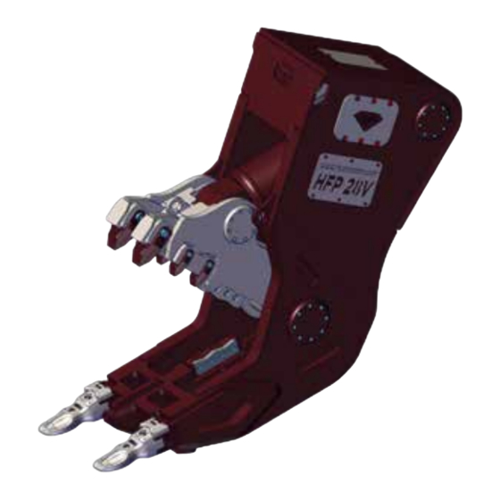
The Secondary pulverizer Series HFP is an attachment that has been fully designed and manufactured by Hydraram for a variety of requirements (demolition, crushing, cutting of scrap and metal profiles). The attachment consists of a main body and the jaws. -
Page 20: Prohibited Uses
4.1.1. Prohibited uses This attachment is exclusively intended for professional use. It is absolutely prohibited for anyone to use the attachment for any purpose other than that expressly allowed and documented. Any improper use of the latter will relieve the manufacturer from any liability for personal or property damage and will void any guarantees. - Page 21 HFP-4V HFP-7V HFP-15V HFP-22V HFP-28V HFP-35V HFP-48V HFP-72V 4 - 7 Excavatorclass 6 - 10 13 - 17 18 - 25 25 - 32 33 - 45 42 - 68 65 - 85 Weight 1420 2180 2820 3420 4760 6980 Jaw opening 1100 1250...
- Page 22 Fixed pulverizer with rotation HFP-15RV HFP-22RV HFP-28RV HFP-35RV Excavatorclass 16 - 22 23 - 28 25 - 32 36 - 50 Weight 1640 2425 3340 3750 Jaw opening Cutter length Workingpressure Oilflow at open/close L/min. 120-200 200 - 300 250 - 350 300 - 400 Workingpressure rotation Oilflow rotation...
- Page 23 Fixed pulverizer POWERBOOSTER HFP-15P HFP-21P HFP-26PR HFP-30P HFP-33PR HFP-36P Excavator class 13 – 17 18 – 25 23 – 28 25 – 32 33 - 45 33 – 45 Weight 1480 2170 2680 2880 3490 3660 1600 1845 2215 1955 2365 2080 Cutter length...
-
Page 24: Installation
5. Installation 5.1. Moving and handling The attachment may be shipped on wooden beams or pallets, or in a crate, depending on the destination and the customer’s request. Lifting the attachment in its packaging using cables and a gantry crane or a forklift truck. The attachment unloading, lifting and handling operations must be carried out by personnel qualified to operate lifting equipment. -
Page 25: Storage
IMPORTANT When the attachment arrives, the user must check it for any damage (breakage or significant dents) that may have occurred during shipping or unloading. If damage has occurred, immediately make it known to the transporter and add the words “ACCEPTED WITH RESERVATIONS” to the delivery document. -
Page 26: Mounting The Attachment
5.4. Mounting the attachment Mounting begins with the attachment supported stably on the ground with the operating machine’s engine stopped and parking brakes engaged. If the attachment is supplied without the operating machine fitting, it is the customer/operator’s responsibility to provide for the application of a suitable connection fitting corresponding to the characteristics of the operating machine. -
Page 27: Use On Construction Cranes
5.5. Use on construction cranes The range of possible applications for the HFP Series hydraulic demolition attachments includes installation on construction cranes. Below is a list of operating systems, rules and requirements that must be respected when using the attachment in this way. - Page 28 TECHNICAL CONNECTION SPECIFICATIONS Hydraulic connections Attachment Operating machine Power Rotation Drainage HFP SERIES optional optional optional 3/4” 3/4” S 25 HFP-7V (36x2) HFP-15V 1” HFP-22V 1” S 30 (42x2) HFP-28V 6000 HFP-35V HFP-22RV 1” 1” S 30 3/8” 3/8” S 16...
-
Page 29: Stopping And Disassembly
The operating machine output pressure and flow rate must always conform to the requirements of the attachment in use (see 4.3. Technical Specifications). If this is not possible, the system must be equipped with reduction valves (contact the manufacturer of the operating machine or a specialized workshop). Do not use the attachment without check that the pressure and oil flow of the operating machine are those required. -
Page 30: Using The Attachment
• Insert the safety pin (A) in seats (C) and (D) • Fix everything using a cotter pin • For transport, use the lifting points indicated by the stickers. • Place the attachment in a dry, protected place. 6. Using the attachment 6.1. -
Page 31: Stopping The Attachment
• Once the crushing operation has been completed, move the operating machine away from the work site, making sure that there are no unstable parts or pieces in positions that are potentially dangerous for the operators assigned to clear away and/or load the material. 6.3. -
Page 32: Regular Maintenance
weight of people; • Once the work is complete, replace and secure all the safety panels that were removed and/or opened correctly; • Carefully clean individual components with an appropriate degreaser and without using compressed air (as this just moves dirt around); •... - Page 33 WARNING! Wear P.P.E. whenever carrying out scheduled maintenance. Scheduled maintenance table The machine must be isolated for maintenance. Operation Interval Every 8 hours Lubricate the hinges and the slew ring (if present) and replace any damaged greasers. Every 8 hours Check that the screws of the connection saddle are not loose or damaged.
-
Page 34: Lubrication
7.4.1. Lubrication The attachment must be lubricated at all the greasing points indicated by G on the image below, or by stickers on the respective plate. Lubrication intervals must be determined based on operating conditions. The attachment must be re-lubricated before or after prolonged periods of inactivity. -
Page 35: Table Of Lubricants
7.4.2. Table of lubricants We have checked the compatibility of the greases shown in the table with the materials used for spacers and gaskets and consider them suitable for use in the bearings. For this reason, if the user wishes to use lubricants differing from those shown here they must obtain confirmation from the supplier or maker that the selected lubricant is suitable for use and that its specifications are at least equivalent to those of the products listed in the table. -
Page 36: Tightening The Screws
7.4.3. Tightening the screws Tightening must be performed exclusively by specialised technicians using a torque wrench and applying the torque values indicated in the table Tightening Torques and Stresses. The screws may only be re- tightened once, after which they must be replaced. The table below applies to nuts and triangular-profile screws with large pitch metric threads as a function of their UNI strength class. -
Page 37: Rotation And Replacement Of Cutting Edges
7.4.4. Rotation and replacement of cutting edges Removing the cutting edges of the attachment requires turning off the operating machine and wearing appropriate P.P.E. Remove the screws fixing the cutting edges of the attachment. Remove the cutting edge from its seat as shown on the image. 2. -
Page 38: Extraordinary Maintenance
To replace worn front teeth (4), remove the fixing screws (2) and relative bolts (5). 2. Remove the worn teeth from their seat. 3. Insert new interchangeable teeth and tighten with new screws. 4. To replace the remaining worn teeth (3), unscrew them one at a time, taking care to insert the corresponding new tooth, before moving onto the next one in order to avoid... -
Page 39: Anti-Wear Material
7.5.1. Anti-wear material Periodically, check the state of deterioration of the claws on the attachment and replace the anti-wear material when necessary. The material must be applied in accordance with the instructions below. WARNING! • Before replacing the material, carefully remove any paint residues to avoid releasing toxic vapours. -
Page 40: Diagnostics And Troubleshooting
7.6. Diagnostics and troubleshooting General requirements In the event of an attachment malfunction, request a specialised technician to carry out a troubleshooting investigation on it or call the manufacturer’s technical support service. Possible cause Possible solution Problem The operating machine is not Check the pressures on the ... - Page 41 Possible cause Possible solution Problem Operating machine pressure not Adjust the pressure of the operating correctly calibrated. machine. Rotation motor damaged. Replace the motor. The attachment doesn’t rotate (if applicable) Motor valve damaged. Replace the motor valve. Flow regulation valve closed.
-
Page 42: Spare Parts
Always use original replacement parts. We strongly advise against the use of non-original parts and, in the event non-original spare parts are use Hydraram may not be held responsible for the consequences of resulting breakages, malfunctions, injuries to personnel or damage to property. In addition, in such cases, the guarantee will be rendered null and void (if still valid). - Page 43 Hydraram B.V. Meander 7, 9231DB, Surhuisterveen Holland Tel : +31 512 365 981 - info@hydraram.com www.hydraram.com...
Need help?
Do you have a question about the HFP Series and is the answer not in the manual?
Questions and answers