Table of Contents
Advertisement
Quick Links
Advertisement
Table of Contents

Summary of Contents for Safire SF-VIMOD-CAM-2
- Page 1 Door Station Installation Guide...
- Page 2 Door Station Installation Guide Symbol Conventions The symbols that may be found in this document are defined as follows. Symbol Description Indicates a hazardous situation which, if not avoided, will or could Danger result in death or serious injury. Indicates a potentially hazardous situation which, if not avoided, Caution could result in equipment damage, data loss, performance degradation, or unexpected results.
-
Page 3: Table Of Contents
Door Station Installation Guide Contents Chapter 1 Appearance ........................1 Chapter 2 Terminal and Wiring ...................... 3 2.1 Terminal Description......................3 2.2 Wiring Description ......................4 2.2.1 Power Supply Wiring ....................4 2.2.2 Door Lock Wiring ....................5 2.2.3 Door Magnetic Wiring .................... 6 2.2.4 Exit Button Wiring .................... -
Page 4: Chapter 1 Appearance
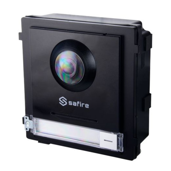
Door Station Installation Guide Chapter 1 Appearance Front and Side Panel Figure 1-1 Front and Side Panel Table 1-1 Appearance Description Description Microphone Low Illumination IR Supplement Light Built-in Camera Loudspeaker Call Button Nametag TAMPER... - Page 5 Door Station Installation Guide Bottom Panel Figure 1-2 Bottom Panel Table 1-2 Appearance Description Description Network Interface Module-connecting Interface (output) Terminals...
-
Page 6: Chapter 2 Terminal And Wiring
Door Station Installation Guide Chapter 2 Terminal and Wiring 2.1 Terminal Description Figure 2-1 Terminals and Interfaces Table 2-1 Descriptions of Terminals and Interfaces Interface Description Door Lock Relay Output (NC) Door Lock Relay Output (NO) Common Interface Door Lock Relay Output (NC) Door Lock Relay Output (NO) Grounding 12 VDC... -
Page 7: Wiring Description
Door Station Installation Guide Interface Description Power and Network Interface 2.2 Wiring Description 2.2.1 Power Supply Wiring Caution Make sure all the related equipment is power-off during the installation. Wire the devices with power supply cables as picture shown below. Door station should be connected to CH6 of the video/audio distributor with two-wire cables. -
Page 8: Door Lock Wiring
Door Station Installation Guide 2.2.2 Door Lock Wiring Figure 2-3 Door Lock Wiring Note ● Terminal NC1/COM is set as default for accessing magnetic lock/electric bolt; terminal NO2/COM is set as default for accessing electric strike. ● Lock should be powered by itself. Max. voltage and current for relay is 30V and 1A. -
Page 9: Door Magnetic Wiring
Door Station Installation Guide 2.2.3 Door Magnetic Wiring Figure 2-4 Door Magnetic Wiring Note AIN1 and AIN2 are defaulted to connect door magnetic. Door magnetic connected to AIN1 detects status of the lock that connected to NC1/NO1; Door magnetic connected to AIN2 detects the status of the lock connected to NC2/NO2. -
Page 10: Exit Button Wiring
Door Station Installation Guide 2.2.4 Exit Button Wiring Figure 2-5 Exit Button Wiring Note AIN3 and AIN4 are set as default for connecting exit button. Exit button connected to AIN3 opens the lock connected to NC1/NO1; Exit button connected to AIN4 controls the lock that connected to NC2/NO2. -
Page 11: Chapter 3 Installation
Door Station Installation Guide Chapter 3 Installation Note ● Make sure the device in the package is in good condition and all the assembly parts are included. ● Make sure the place for surface mounting is flat. ● Make sure all the related equipment is power-off during the installation. ●... -
Page 12: One-Module Installation
Door Station Installation Guide Table 3-1 Description Sub Module Digit 1 Digit 2 Digit 3 Digit 4 Address 3.2 One-Module Installation 3.2.1 Surface Mounting Before You Start Figure 3-2 Mounting Frame... - Page 13 Door Station Installation Guide Note ● The dimension of one module mounting frame is: 117(W)×107(H)×32.7(D) mm. ● The dimensions above are for reference only. The actual size can be slightly different from the theoretical dimension. Steps 1. Paste the installation Sticker 1 onto the wall. Make sure the sticker is placed leveled via measuring with the gradienter.
- Page 14 Door Station Installation Guide 4. Fix the mounting frame onto the wall with 4 expansion bolts. Figure 3-4 Fix the Mounting Frame 5. Connect the cables to the corresponding interfaces of the main unit and insert it into the frame. Figure 3-5 Insert the Main Unit 6.
-
Page 15: Flush Mounting
Door Station Installation Guide Figure 3-6 Fix the Cover 3.2.2 Flush Mounting Before You Start Figure 3-7 Front and Side View of the Gang Box... - Page 16 Door Station Installation Guide Figure 3-8 Gang Box Note ● The dimension of one-module gang box is: 115(W)×134(H)×56(D) mm. ● The dimensions above are for reference only. The actual size can be slightly different from the theoretical dimension. Steps 1. Cave the installation hole, and pull the cable out. Note ●...
- Page 17 Door Station Installation Guide Figure 3-9 Cave the Installation Hole 2. Remove the plastic sheet in the cable entry. 3. Insert the gang box into the hole and pull out the cables through the cable entry. Mark the screw holes' position with a marker, and take out the gang box. Figure 3-10 Mark the Screw Holes 4.
- Page 18 Door Station Installation Guide Figure 3-11 Fix the Gang Box 6. Fill and level up the gap between the gang box and wall with concrete. Remove the 4 mounting ears with tool after concrete is dry. Figure 3-12 Remove the Mounting Ears 7.
- Page 19 Door Station Installation Guide Figure 3-13 Insert the Main Unit 9. Use the hexagon wrench in the package fix the cover. Figure 3-14 Fix the Cover...
-
Page 20: Two-Module Installation
Door Station Installation Guide 3.3 Two-Module Installation 3.3.1 Two-Module Surface Mounting Before You Start Figure 3-15 Mounting Frame Note ● The dimension of two-module mounting frame (W × H × D) is: 219 mm × 107 mm × 32.7 mm. ●... - Page 21 Door Station Installation Guide Figure 3-16 Drill Screw Holes 3. Remove the sticker and insert the expansion sleeves into the screw holes. 4. Fix the mounting frame onto the wall with 4 expansion bolts. Figure 3-17 Fix the Mounting Frame 5.
- Page 22 Door Station Installation Guide Figure 3-18 Placement of Lines 6. Connect the cables. 1) Connect the lines and module-connecting line to the corresponding interfaces of the main unit, then place the main unit into the upper grid. 2) Connect the other end of the module-connecting line to the input interface of the sub module.
- Page 23 Door Station Installation Guide Figure 3-19 Line Connection Effect Picture 7. Insert the modules into the frame after wiring. The main unit must be placed in the top grid. Figure 3-20 Insert the Modules 8. Use the hexagon wrench in the package to fix the cover onto the frame.
-
Page 24: Two-Module Flush Mounting
Door Station Installation Guide Figure 3-21 Fix the Cover 3.3.2 Two-Module Flush Mounting Before You Start Figure 3-22 Gang Box... - Page 25 Door Station Installation Guide Note The dimension of two-module gang box is: 237 (W) × 134 (H) × 56 (D) mm. The dimension is for reference only. Steps 1. Drill the installation hole, and pull the cable out. Note ● The suggested dimension of installation hole is 220 (W) × 108 (H) × 45.5 (D) mm. ●...
- Page 26 Door Station Installation Guide Figure 3-24 Mark the Screw Holes 4. Drill 4 holes according to the marks on the wall, and insert the expansion sleeves into the screw holes. The suggested size of hole is 6 (diameter) × 45 (depth) mm. 5.
- Page 27 Door Station Installation Guide Figure 3-26 Remove the Mounting Ears 7. Connect cables and insert the modules. 1) Connect Cable 1 and one end of Cable 2 to the corresponding interfaces of the main unit, then insert the main unit into the upper grid. 2) Connect the other end of Cable 2 to the input interface of the sub module.
- Page 28 Door Station Installation Guide Note Cable 1 refers to the cables pulled out from the wall that connected to the main unit. Cable 2 refers to the module-connecting line in the accessory package. 8. Fix the cover with 2 socket head cap screws by using a hexagon wrench (supplied). Figure 3-28 Fix the Cover...
-
Page 29: Three-Module Installation
Door Station Installation Guide 3.4 Three-Module Installation 3.4.1 Three-Module Surface Installation Before You Start Figure 3-29 Mounting Frame Note ● The dimension of two-module mounting frame (W × H × D) is: 320.8 mm × 107 mm × 32.7 mm. ●... - Page 30 Door Station Installation Guide Figure 3-30 Drill Screw Holes 3. Remove the sticker and insert the expansion sleeves into the screw holes. 4. Fix the mounting frame onto the wall with 4 expansion bolts. Figure 3-31 Fix the Mounting Frame...
- Page 31 Door Station Installation Guide Note The mounting frame should be placed exactly as shown below for this step. The tamper plate should be at the low right of the first grid. Figure 3-32 Mounting Frame 5. Thread the module-connecting line across the thread holes of the frame. Pass the main unit connecting line across the thread hole to the top grid.
- Page 32 Door Station Installation Guide 1) Connect the lines and module-connecting line 1 to the corresponding interfaces of the main unit, then place the main unit into the upper grid. 2) Connect the other end of the module-connecting line 1 to the input interface of the sub module.
- Page 33 Door Station Installation Guide Figure 3-36 Fix the Cover...
-
Page 34: Three-Module Flush Mounting
Door Station Installation Guide 3.4.2 Three-Module Flush Mounting Before You Start Figure 3-37 Gang Box Note The dimension of one-module gang box is: 338.8(W)×134(H)×56(D) mm.The dimensions above are for reference only. The actual size can be slightly different from the theoretical dimension. Steps 1. - Page 35 Door Station Installation Guide Figure 3-38 Cave the Installation Hole 2. Select a cable entry and remove the plastic sheet. 3. Mark the gang box screw holes on the wall. 1) Route the cables through the gang box hole. 2) Insert the gang box into the installation hole. 3) Mark the gang box screw holes' position with a marker, and take out the gang box.
- Page 36 Door Station Installation Guide Figure 3-40 Fix the Gang Box 6. Fill the gap between the gang box and wall with concrete. Remove the mounting ears with tool after concrete is dry. Figure 3-41 Remove the Mounting Ears 7. Connect cables and insert the modules. 1) Connect Cable 1 and one end of Cable 2 to the corresponding interfaces of the main unit, then insert the main unit into the upper grid.
- Page 37 Door Station Installation Guide Figure 3-42 Connect Cables and Insert Modules Note Cable 1 refers to the cables pulled out from the wall that connected to the main unit. Cable 2 and Cable 3 refer to the module-connecting line in the accessory package. 8.
-
Page 38: More-Than-Three Module Installation
Door Station Installation Guide 3.5 More-Than-Three Module Installation 3.5.1 More-than-Three Module Surface Mounting Before You Start Figure 3-44 Mounting Frame Note ● It takes two three-module mounting frames. The dimension of three-module mounting frame (W × H × D) is: 320.8 mm × 107 mm × 32.7 mm. ●... - Page 39 Door Station Installation Guide Figure 3-45 Drill Screw Holes 4. Remove the stickers and insert the expansion sleeves into the screw holes. 5. Thread the module-connecting line (400 mm) and grounding line across the thread hole of both frames. Figure 3-46 Place the Grounding Line and Module-Connecting Line...
- Page 40 Door Station Installation Guide Note ● There are 6 module-connecting lines in the package: 190 mm × 4 and 400 mm × 2. ● Take the 400 mm module-connecting line for this step. ● The green-yellow line in the package is for grounding. 6.
- Page 41 Door Station Installation Guide 1) Connect the cables from the wall and module-connecting line 1 to the corresponding interfaces of the main unit, then place the main unit into the upper grid. 2) Connect the other end of the module-connecting line 1 to the input interface of the sub module.
- Page 42 Door Station Installation Guide Figure 3-50 Insert the Modules 10. Pull the grounding line out and fixed its two end to the screw on the cover. Figure 3-51 Connect the Grounding Line to the Cover 11. Use the hexagon wrench in the package to fix the cover onto the frame.
- Page 43 Door Station Installation Guide Figure 3-52 Fix the Cover...
-
Page 44: More-Than-Three Module Flush Mounting
Door Station Installation Guide 3.5.2 More-Than-Three Module Flush Mounting Before You Start Figure 3-53 Gang Box... - Page 45 Door Station Installation Guide Note It takes two three-module gang boxes. The dimension of the gang box is: 338.8 (W) × 134 (H) × 56 (D) mm. The dimension is for reference only. Steps 1. Drill the installation hole, and pull the cable out.The suggested dimension of installation hole is 321.8 (W) ×...
- Page 46 Door Station Installation Guide Figure 3-55 Connect Two Gang Boxes 3. Select a cable entry and remove the plastic sheet. 4. Remove the plastic sheets on the side of the gang boxes (shown as 1 and 2) below: Figure 3-56 Remove the Plastic Sheets 5.
- Page 47 Door Station Installation Guide Figure 3-57 Mark the Screw Holes 6. Drill 8 holes according to the marks on the wall, and insert the expansion sleeves into the screw holes. The suggested size of hole is 6 (diameter) × 45 (depth) mm. 7.
- Page 48 Door Station Installation Guide Figure 3-59 Remove the Mounting Ears Note The green-yellow line in the package is for grounding. 9. Connect cables and insert the modules. 1) Connect Cable 1 and one end of Cable 2 to the corresponding interfaces of the Main Unit, then place the Main Unit into the upper grid of the left gang box.
- Page 49 Door Station Installation Guide Figure 3-60 Install Mounting Frame The cables connect to each module shown as below. Figure 3-61 Cables Connection Note ● Cable 2,3,5 and 6 are the module-connecting lines (190 mm) in the package. ● Cable 4 is the module-connecting line (400 mm) in the package. ●...
- Page 50 Door Station Installation Guide Figure 3-62 Connect the Grounding Line to the Cover 11. Fix the cover with 2 socket head cap screws by using a hexagon wrench (supplied).
- Page 51 Door Station Installation Guide Figure 3-63 Fix the Cover...
- Page 52 UD13576N...
Need help?
Do you have a question about the SF-VIMOD-CAM-2 and is the answer not in the manual?
Questions and answers