
Summary of Contents for Ogden ETR-9040
- Page 1 MANUAL NO. 54 Model ETR-9040 Microprocessor Based Limit Control INSTRUCTION MANUAL...
- Page 2 WARNING SYMBOL! This Symbol calls attention to an operating procedure or practice which, if not correctly performed or adhered to, could result in personal injury or damage to the product or system. Do not proceed beyond a warning symbol until the indicated conditions are fully understood and met.
-
Page 3: Table Of Contents
Section 7: TROUBLESHOOTING ..20, 21 Section 1: INTRODUCTION The OGDEN ETR-9040 limit control is an over tempera- Digital communication RS-485 is available as an addi- ture protection or a high limit safety device with a tional option. -
Page 4: Section 2: Catalog Numbering System
Section 2: CATALOG NUMBERING SYSTEM ETR-9040- Option Power Input Signal Input Output 1 0 None 4 90-264VAC, 50/60Hz 1 Standard Input 1 Form C Relay Rated 1 Form A Relay 5 11-26VAC or VDC Thermocouple J, K, 2A/240VAC 2A/240VAC T, E, B, R, S, N, L... - Page 5 Common Mode Data Communications Rejection Ratio Interface: RS-485 (up to 247 units) (CMRR): 120db Protocol: Modbus protocol RTU mode Sensor Break Address: 1 - 247 Detection: Sensor open for TC, RTD and mV Baud Rate: 0.3 ~ 38.4 Kbits/sec inputs, below 1mA for 4-10 mA input, below 0.25V Data Bits: 8 bits for 1-5V input, unavailable for other inputs...
-
Page 6: Section 4: Installation
• It is recommended that power to these instruments described by OSHA Standards. Units suspected of be protected by fuses and circuit breakers rated at being faulty must be removed and returned to Ogden for the minimum value possible. inspection and/or repair. They contain no user servicea- •... -
Page 7: Wiring Diagrams
Connect terminals as shown below in Fig. 4.3. The sponds with the power rating indicated on the product ETR-9040 is equipped to operate at either 11-26VAC/VDC label before connecting power to the unit. All wiring or 90-264VAC. Check that the installation voltage corre- must conform to national and local electric codes. - Page 8 Max. 2A Resistive 120V/240V Main Supply Thermocouple — To Controller Output Figure 4.4 Example of Wiring Connections for RTD Sensor Connections ETR-9040-4110 with Relay Output (ETR-9040-4160 with Triac Output) 120V/240V Main Supply To Controller Output Three Phase Heater Power Three Phase...
- Page 9 Temperature Control — — — ETR-9090-132 Rear View Reset Limit Control Button Heater — ETR-9040-411B Rear View Mechanical Contactor Figure 4.7 Example of Wiring Limit Control ETR-9040 with a Manual Reset to Protect the Process Being Controlled by an ETR-9090...
- Page 10 Table 4.2 Heating Output Wiring Function Internal Device: Terminals: External Connection: 1. Relay (Isolated). To line 240VAC max. Relay contact is closed during LOAD MAX 3A ON phase of output cycle. (CTRL lamp ON) 2. Current (Isolated. Input impedance of control 4-20mA Reverse acting current (The device, MAX.
-
Page 11: Output 2 Wiring
Output 2 Wiring Max. 2A Resistive LOAD – Sensor 120V/240V Supply Transmitter Figure 4.9 DC Power Supply Output Figure 4.8 Relay or Triac Output LOAD 120V/240V Supply Figure 4.10 Pulsed Voltage to Drive SSR Two-line Transmitter OUT2 = DC Power Supply Caution: To avoid damage do not use the DC Power Supply beyond its rating current . -
Page 12: Rs-485 Wiring
Figure 4.12 RS-485 Wiring RS-485 to RS-232 Network Adaptor SNA10A or SNA10B RS-485 RS-232 Shielded Twisted-Pair Wire DB9 Serial Cable Max. 247 units can be linked Terminator 220 ohms/0.5W... -
Page 13: Section 5: Operation
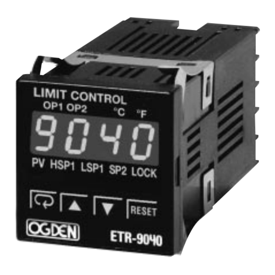
Section 5: OPERATION Keys and Display TOUCHKEYS DESCRIPTION FUNCTION 1. Select a point to be displayed Scroll Key 2. Select a parameter to be viewed or adjusted 3. Advance display from a parameter code to the next parameter code Enter Key Press the scroll key for 4 seconds, the display will Press then enter the setup menu. -
Page 14: Adjustment Flow Chart
Menu Overview Setup Mode Press for 4 sec. Process INPT Input type Process value Value UNIT Process units or SAFE RESO Display resolution Low scale value for IN.LO linear input High Limit High scale value for IN.HI linear input HSP1 Value set point 1 SHIF PV shift (offset) value value... -
Page 15: Menu Descriptions
Table 5.1 Index Code (Menu) Descriptions: NOTE: Further parameter definitions (Do not disconnect power for at least 12 seconds after changing any control values. on pages 14 and 15 This allows the parameters to be entered into memory.) Index Description Default Index Description... - Page 16 In certain applications the process value is too unstable UPPER LIMIT OF LSP1 to be read. To improve this, a programmable low pass fil- ter incorporated in the ETR-9040 can be used. This is a OUTPUT2 FUNCTION first order filter with a time constant specified by the FILT parameter which is contained in the set up menu.
- Page 17 Display Mode Reference Data The DISP in the set up menu is used to select the dis- The are three different types of reference data con- play format under normal conditions. If PV is selected, tained in the set up menu. The reference data is read- the display will indicate the process value.
-
Page 18: Limit Operation
Limit Control Operation High Limit Operation If Hi. is selected for OUT1, the unit will perform high limit control. When power is applied, the OUT1 relay is de-ener- gized. After the 6.5 second self-test period if the process is below the high limit set point (HSP1), the output 1 relay will be energized and the OP1 indicator will go off. -
Page 19: Alarm Operation
DCPS for OUT2 in set-up menu. RS-232 port. In other words, a PC with 4 comm ports Limit Annunciator can communicate with 988 units. Ogden uses a If L.AN (Limit Annunciator) is selected for OUT2, output 2 Universal MODBUS RTU MODE protocol to commu- will act as a Limit Annunciator. -
Page 20: Display Shift
Display Shift components of the system, the sensor could not be In certain applications it is desirable to shift the con- placed any closer to the work. trollers indicated value from its actual value. This can be easily accomplished with this control by using the dis- Thermal gradients (different temperatures) are common play shift function. -
Page 21: Section 6: Calibration Procedure
Section 6: CALIBRATION Do not proceed through this section unless there 2. A test chamber providing 25°C - 0°C temperature is a definite need to re-calibrate the controller. range Otherwise, all previous calibration data will be Equipment needed for automatic calibration: lost. -
Page 22: Section 7: Troubleshooting
Section 7: TROUBLESHOOTING THIS PROCEDURE REQUIRES ACCESS TO THE CIRCUITRY OF A LIVE POWER UNIT. WARNING! DANGEROUS ACCIDENTAL CONTACT WITH LINE VOLTAGE IS POSSIBLE. ONLY QUALIFIED PERSONNEL ARE TO PERFORM THESE PROCEDURES. POTENTIALLY LETHAL VOLTAGES ARE PRESENT. Experience has proven that many control problems are not caused by a defective instrument. See chart below and Table 7.1 on the next page for some of the other common causes of failures: Short across terminals. - Page 23 Table 7.1 Troubleshooting Table 7.1 Troubleshooting Symptom Probable Cause(s) Solution(s) 1.) LED’s will not light. —No power to instrument. —Check power line connections. —Power supply defective. —Replace power supply board. 2.) Some segments of the display or —LED display or LED Lamp defec- —Replace LED display or LED lamp.
- Page 24 © Ogden Manufacturing Co. 2003 OGDEN, ETR, ETR-9090, ETR-9200 and SMARTER LOGIC are Registered Trademarks of Ogden Manufacturing Co. MARCA REGISTRADA Specifications subject to change without notice.
Need help?
Do you have a question about the ETR-9040 and is the answer not in the manual?
Questions and answers