Table of Contents
Advertisement
Quick Links
Advertisement
Table of Contents

Subscribe to Our Youtube Channel
Related Manuals for Intellisystem ThermalTronix TT-1025EX-MIL

Summary of Contents for Intellisystem ThermalTronix TT-1025EX-MIL
- Page 1 ThermalTronix TT-1025EX-MIL Thermal Imaging System User Manual...
-
Page 2: Table Of Contents
Content CONTENT ..............................1 SECURITY INFORMATIONS ......................... 2 USING LIMITS ............................. 2 INTRODUCTION ............................3 OUTLOOK ..............................3 TECHNICAL SPECIFICATIONS ........................4 ACCESSORIES .............................. 5 INTERFACE ..............................6 INSTALLATION AND WIRING ........................7 TROUBLE SHOOTING ..........................10... -
Page 3: Security Informations
Security informations The security points below will ensure the explorer system against operational damagement. 1)please read the operation manual and the security information; please follow the operation manual to install the thermal imaging system. 2) Please keep the system in a optimized condition while it is not in use. 3) Please obey the security information;... -
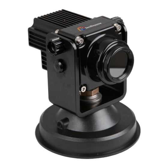
Page 4: Introduction
Introduction The thermal imaging system is a traffic used product developed by Intellisystem Technologies Company. The product uses uncooled bolometer FPA and real-time imaging circuit; it is suitable in low light or night environment application. The product can warn the driver with objects, which can not be seen by human eyes, it will not influenced by car lights. -
Page 5: Technical Specifications
Technical specifications Items ThermalTronix TT-1025EX-MIL Detector Uncooled bolometer spectrum 8~14μm Pixal arrays 384*288 Resolution 35μm Detector F.O.V 33°× 25°(35μm) I.F.O.V 1.84 mrad(35μm) NETD ≤100mk@30℃(35μm) Image frequency 25Hz focusing Fixed focus(≥25m) Starting up time ≤15 System Automatic heater Turn on when the temperature ≤+4ºC Target Environment:15℃,1atm,... -
Page 6: Accessories
Accessories The accessories includes: Items Quantity Operation manual Security case Inner case Thermal imaging system Screen Installing pack Connecting cable... -
Page 7: Interface
Interface The imaging system includes screen interface, external power, and car power supply cable. 1. Power supply Car power supply Figure 2 Car power supply cable Power supply:DC12V 2. Screen Figure 3 Screen interface Display:CVBS Power:DC12V... -
Page 8: Installation And Wiring
3. Thermal imaging system output interface Figure 4 thermal imaging system output Display:CVBS Power:DC12V Installation and wiring 1. Hold the ears of the thermal imaging system interface of the connecting cable, insert the cable connecter to the 26 pin port. Make sure the connecting dimension is correct. - Page 9 Figure 6 Frame Size...
- Page 10 Figure 7 Thermal imaging system Size 3、Connect the cable with the video and power supply interface, the car power supply is shown as Figure 2. Turn on the power supply and wait for the screen display thermal images. Operation steps: 1....
-
Page 11: Trouble Shooting
Trouble shooting Trouble Cause and solution System delay protection →wait for 5 seconds, turn on again The system can not turn Power supply not connected →check the power supply The screen not turn on →check the screen interface ...
Need help?
Do you have a question about the ThermalTronix TT-1025EX-MIL and is the answer not in the manual?
Questions and answers