
Related Manuals for BTI Wireless RU4370

Summary of Contents for BTI Wireless RU4370
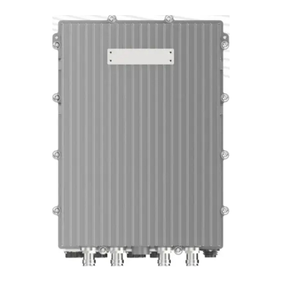
- Page 1 RU4370 User Manual RU4370 User Manual 4T4R Digital Radios High Output Power Outdoor Rated Copyright © 2021 BTI WIRELESS All rights reserved.
- Page 2 The information in this document is therefore provided on an “as is” basis without warranty and is subject to change without further notice and cannot be construed as a commitment by BTI Wireless. The products mentioned in this document are identified by the names, trademarks, service marks and logos of their respective companies or organizations and may not be used in any advertising or publicity or in any other way whatsoever without the prior written consent of those companies or organizations and BTI Wireless.
-
Page 3: Table Of Contents
Environmental.................................. 4 Warning Marks................................. 6 Preparation....................................8 Unpacking and Inspection..............................8 Tools....................................8 Installation of the RU4370............................... 9 RU4370 Accessories................................. 9 Wall Installation (Back on the Wall)..........................10 Wall Installation (Side on the Wall)..........................15 Pole Installation................................19 Copyright © 2021 BTI WIRELESS All rights reserved. -
Page 4: General
coverage. Pick an ideal easy-to-reach location for installation convenience. Verify that there is a minimum of a 80cm radius of space around RU4370 system equipment for the convenience of maintenance and on-site inspection. Environmental Humidity and temperature have adverse efforts on the reliability of the RU4370 system. Therefore, it is highly recommended to install the equipment in locations with stable humidity, temperature, and ventilating. - Page 5 RU4370 User Manual Maximum humidity: 100% Temperature range: -40 to 55℃ Copyright © 2021 BTI WIRELESS All rights reserved.
-
Page 6: Warning Marks
ALWAYS disconnect all lines and power connections before servicing or disassembling this equipment. NEVER touch the surface after the devices power on. For performance and safety reasons, NEVER disassemble and remodel the devices. Copyright © 2021 BTI WIRELESS All rights reserved. - Page 7 RU4370 User Manual Copyright © 2021 BTI WIRELESS All rights reserved.
-
Page 8: Preparation
3. Ensure that all equipment and accessories have no damage. If there is any damage, contact your BTI service agent. Tools Electric drill, cross head screwdriver, side cutters, ladder, and other tools are needed for RU4370 installation which is not offered from BTI for now. Customers to provide these tools themselves. -
Page 9: Installation Of The Ru4370
RU4370 User Manual Installation of the RU4370 RU4370 Accessories Figure 1. RU4370 Accessories Copyright © 2021 BTI WIRELESS All rights reserved. -
Page 10: Wall Installation (Back On The Wall)
Attach and fasten the handle to the side of RU4370 with screws M6×14 using T5 Wrench. Attach and fasten the Bracket I to the back of RU4370 with screws M6×14 using T5 Wrench. Copyright © 2021 BTI WIRELESS All rights reserved. - Page 11 RU4370 User Manual Mark the position of the drilling holes in the mounting Bracket II. Note: R=13mm. Drill 4 holes at the marked positions. Note: H=70mm Copyright © 2021 BTI WIRELESS All rights reserved.
- Page 12 Attach the dowels, expansion screws or the like and fasten the Bracket II to the wall. Tips: use Bracket II as a reference to control each devices’ separation distance before hanging and locking RU4370 up. Hang the RU4370 on the mounting bracket II and fasten with nuts M10.
- Page 13 RU4370 User Manual Fasten the Bracket I and II with screws M6×14. Connect and lock the power cable at the RU4370 rear side Copyright © 2021 BTI WIRELESS All rights reserved.
- Page 14 RU4370 User Manual Connect and screw the ground cable at the RU4370’s left side Copyright © 2021 BTI WIRELESS All rights reserved.
-
Page 15: Wall Installation (Side On The Wall)
Attach and fasten the handle to the side of RU4370 with screws M6×14 using T5 Wrench. Figure 2. Attach and fasten the Bracket I to the left side of RU4370 with screws M6×14 using T5 Wrench. Copyright © 2021 BTI WIRELESS All rights reserved. - Page 16 RU4370 User Manual Mark the position of the drilling holes in the mounting Bracket II. Note: R=13mm. Drill 4 holes at the marked positions. Note: H=70mm. Copyright © 2021 BTI WIRELESS All rights reserved.
- Page 17 Attach the dowels, expansion screws or the like and fasten the Bracket II to the wall. Tips: use Bracket II as a reference to control each devices’ separation distance before hanging and locking RU4370 up. Hang the RU4370 on the mounting bracket II and fasten with nuts M10.
- Page 18 RU4370 User Manual Fasten the Bracket I and II with screws M6×14. Copyright © 2021 BTI WIRELESS All rights reserved.
-
Page 19: Pole Installation
Install the handle and Bracket I to the back of RU4370. Install the bracket II and Bracket III to the pole. Hang the RU4370 on the mounting bracket and fasten with nuts M10. Connect the ground cable and power cable. - Page 20 —Increase the separation between the equipment and receiver. —Connect the equipment into an outlet on a circuit different from that to which the receiver is connected. —Consult the dealer or an experienced radio/TV technician for help. Copyright © 2021 BTI WIRELESS All rights reserved.
Need help?
Do you have a question about the RU4370 and is the answer not in the manual?
Questions and answers