Table of Contents
Advertisement
Quick Links
Advertisement
Table of Contents

Summary of Contents for AVANT CH100
- Page 1 English Wood chipper CH100 Operator’s Manual 2017-...
- Page 2 CAUTION! PRODUCT WARRANTY Avant Tecno Oy provides a 12-months warranty on CH100. CUSTOMER FEEDBACK We are happy to receive your opinions and suggestions for improvements by mail, fax or e-mail. All imple- mented suggestions for improvements will be rewarded.
- Page 3 CH100 EC DECLARATION OF CONFORMITY Translation of original Declaration of Conformity Manufacturer: Farmi Forest Corporation Ahmolantie 6, FIN-74510 IISALMI, Finland Person authorized to compile the technical documentation: Name: Matti Berg Address: Ahmolantie 6, FIN-74510 IISALMI, Finland Commercial name: Farmi Commercial name:...
-
Page 4: Table Of Contents
CH100 TABLE OF CONTENTS GENERAL SAFETY INSTRUCTIONS GENERAL SAFETY INSTRUCTIONS FOR THE CHIPPER STICKERS AND PLATES CH100 - GENERAL DESCRIPTION AND INTENDED USE MOUNTING LIFTING ASSEMBLY INSTRUCTIONS MOUNTING OF THE CHIPPER AND PRE-OPERATION INSPECTIONS MOUNTING OF THE CHIPPER TO AVANT LOADER... -
Page 5: General Safety Instructions
Written authorization must be requested from the manufacturer for any alterations These safety instructions are meant for the owners to the machine. of Avant equipment, as well as those who operate, service or repair it. CAUTION! The instructions help with: •... - Page 6 CH100 TRANSPORT • Never insert any body part into the machine with the engine running. • Before driving with the machine, ensure the safe • If any faults arise that may jeopardize occupational mounting of the machine. Make sure that the safety, turn off the machine.
- Page 7 CH100 • When servicing the machine, place it on a level When replacing or repairing hoses, use original surface and ensure that it cannot be moved. parts or hoses and connectors recommended • Observe the service intervals and annual safety by the manufacturer.
-
Page 8: General Safety Instructions For The Chipper
CH100 GENERAL SAFETY INSTRUCTIONS FOR THE CHIPPER The noise level at the operator’s area may exceed 70 dB(A). Wear hearing protection! DANGER! CAUTION! • Please make sure any machine operator has the required personal protective equipment: safety helmet, protective goggles, cut resistant safety boots and required protective clothing. -
Page 9: Stickers And Plates
CH100 STICKERS AND PLATES These plates and stickers must be found on the chipper. Replace missing plates or stickers immediately. - Page 10 CH100 1. Machine plate CH100 (41010100) 2. CAUTION! Please read the instruction manuals of the machine meticulously before you operate, maintain or repair the machine. During machine operation, please observe the operating and safety instructions. (40147020) 3. (40147000) CAUTION! Before operation, mount the chipper to the quick cou- pling plate of the loader.
- Page 11 CH100 4. Wear personal protective equipment. (40142080). 5. Cutting hazard! (40147010) 6. Lifting point sticker (41014270). 7. SPEED sticker (40141160). Recommended speed range. The rated speed must not be exceeded 8. FARMI Forest sticker (40147090) 9. Sticker “100” (40147490)
-
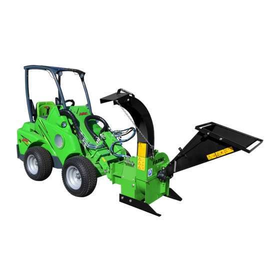
Page 12: Ch100 - General Description And Intended Use
CH100F - GENERAL DESCRIPTION AND INTENDED MAIN COMPONENTS OF THE CH100 1. UPPER CHAMBER 2. LOWER CHAMBER CH100 is a single-disk chipper with two knives used 3. CUTTING DISK for chipping wood with a diameter of up to 100 mm 4. KNIFE (chip size 12 mm). -
Page 13: Mounting
CH100 DIMENSIONS CH 100 100x130 1018 1637 Chipper CH100 TECHNICAL DATA Type disc chipper 0,5-2 m 3 /h Output Chip length 12 mm Max. wood diameter 100 mm Tehon tarve 7,5-30 kW PTO rpm (if PTO driven model) 540 tai 1000 rpm... -
Page 14: Lifting
CH100 ASSEMBLY INSTRUCTIONS LIFTING Lifting points for each machine are marked with hook symbols. WARNING! Lift only using the proper type of lifting device and ensure that it has an appropriate lifting capacity. Check the lifting slings, cables, and chains regularly. -
Page 15: Assembly Instructions
CH100 ASSEMBLY INSTRUCTIONS 1. Attach the feed hopper to the chipper using M12x120 and M12x30 hexagon head bolts and lock nuts. Lock the feed hopper in its operating position. Fig. 1. 2. Mount the discharge pipe to the chipper using two M10 bolts. -
Page 16: Mounting Of The Chipper And Pre-Operation Inspections
CH100 MOUNTING OF THE CHIPPER AND PRE-OPERATION INSPECTIONS 1. For mounting or dismounting the chipper, always turn off the loader and apply the parking brake before entering the area between chipper and loader. 2. Make sure all protective and safety devices of the chipper are installed. -
Page 17: Mounting Of The Chipper To Avant Loader
CH100 MOUNTING THE CHIPPER ON AVANT LOADER Coupling the attachment to the loader is quick and easy, but it must be done carefully. The attachment is fixed to the loader boom by using the quick attach plate and the counterpart on the attachment. I If the attachment is not locked to the loader, it may detach from the loader and cause hazardous situations. - Page 18 CH100 2. Step: • Turn the quick attach plate hydraulically to an obliquely forward position. • Drive the loader onto the attachment. If your loader is equipped with a telescopic boom, you can utilise this. Align the upper pins of the loader’s quick coupling plate so that they are under the corresponding brackets of the attachment.
-
Page 19: Connecting An Disconnecting Hydraulic Hoses
On 200-700 series loaders hydraulic hoses are connected using the multiconnector system. If you want to chan- ge the type of the hydraulic couplings, contact your Avant dealer or service point for instructions or installation services. On old 200-series loaders only conventional quick couplings are available. - Page 20 CH100 CONNECTING THE MULTICONNECTOR SYSTEM: Align the pins of the attachment connector with corresponding holes of the loader connector. The multiconnector will not connect if the attachment connector is upside down. Connect and lock the multiconnector by turning the lever towards the loader.
- Page 21 CH100 HYDRAULIC COUPLINGS ON OLD 200 SERIES LOADERS In a old 200-series machine, the hose can be connected by pushing the fitting in the counterpart. When connecting and disconnecting the 200-series hydraulics quick couplings, you should pay attention to their locking. There is a small groove in the collar of all female fittings, and a small ball near the collar.
-
Page 22: Starting The Chipper
CH100 STARTING THE CHIPPER IMPORTANT! When the chipper is driven with the hydraulic system, Start the machine only after it it is extremely important to slow has been set to working position the loader engine speed to idle and work can be started. Always... -
Page 23: Chipping
CH100 CHIPPING OPERATION OF CHIPPER AND FEED UNIT • Start the chipper. Notice! See section ”Starting the During chipping, please observe chipper”. the following safety instructions: • Set the operating lever to the FEED FORWARD F position. Notice! See picture ”Operating lever functions”. -
Page 24: Emptying The Chipper After Use
CH100 EMPTYING THE CHIPPER AFTER USE MAINTENANCE Let the chipper run empty by operating it for a short time. Before beginning maintenance WARNING! SWIVELING THE FEED HOPPER TO THE TRANSPORT and repair POSITION • place the chipper onto level and hard ground and 1. -
Page 25: Replacing The Bearing
CH100 REPLACING THE BEARING 1. Open the upper chamber. 2. Remove the fastening bolts M10 (7) and the upper bearing housings (6). h=12,7 3. Mark the location of the tightening cone on the shaft. 4. Lift the disk. 5. Bend the claw of the securing ring (3) out from the notch on the axle nut and open the axle nut. -
Page 26: Adjusting The Bearing Clearance
CH100 ADJUSTING THE BEARING CLEARANCE 1. Open the upper chamber. 2. Remove the fastening bolts M10 (7) and the upper bearing housings (6). 3. Remove the grease from the bearing housing. 4. Lift the disk. 5. Bend the claw of the securing ring (3) out from the notch on the axle nut and open the axle nut. - Page 27 CH100 LUBRICATING THE BEARINGS • The bearings are lubricated at the factory, and a similar lubricant should be used for subsequent lubrication (Shell Alvania Grease R 3. or Kendall L427). An excessive amount of grease causes overheating and impairs lubrication.
- Page 28 CH100 100Nm 50Nm 80Nm Fig 10. Checklist for tightening and checking clearances Item Width across flats, Tightening torque, Nm (lbf) mm (inches) 1. Check the knife bolts for tightness. 19 (12/16”) 100 (73 11/16) 2. Check the bearing housing bolts for tightness 17 (11/16”)
-
Page 29: Knife And Anvil Maintenance
CH100 REMOVING THE KNIVES KNIFE AND ANVIL MAINTENANCE 1. Remove the knife fastening bolts (M12). Turn the Read the safety instructions. wrench in such a way that your hands would not The disk continues rotating like hit the knife if the wrench should slip. Fig 12. - Page 30 CH100 SHARPENING THE KNIVES Sharpen all knives equally. This ensures disk balance. Avoid heating the knife during sharpening. KNIFE CAUTION! The knives need sharpening when • the self-feeding of wood has decreased; Fig 13. The profile of a concave knife •...
- Page 31 CH100 REMOVING THE ANVILS ADJUSTING AND CHECKING THE KNIFE-TO-ANVIL CLEARANCE The chipper features both a vertical and horizontal anvil. To remove the anvils, open the fastening bolts The need for adjusting the anvils is determined by the (A) and (B) (M12). The horizontal anvil fastening bolt amount the knives are sharpened.
- Page 32 CH100 knife-to-anvil clearance 1,5-2,0 mm vertical anvil disc Observe the correct position! screw horizontal anvil M12x30 DIN933 10.9 Nord-lock M12 lock washer 2 pcs Fig 18. Cross-section of the disk and knives / anvils...
- Page 33 CH100...
-
Page 34: Ch100 Chipper
CH100 CH100 CHIPPER... - Page 35 CH100 FARMI 100F CH100 CHIPPER FARMI 100 CHIPPER Part Order no Description Remarks 52062041 Screw M12X50 DIN933 88ZN 52117124 Lock nut M12 DIN985 8ZN 52200490 Washer M12 DIN 7349 ZN 52062502 Screw M12X120 DIN931 88ZN 43340934 End plate 52211042 Spring washer...
-
Page 36: Disc, Complete
FARMI 100F CH100 DISC, COMPLETE DISC, COMPLETE Part Order no Description Remarks 33620070 Disc 43620080 Knife 52214269 Lock washer M12 NORD-LOCK 52091839 Screw M12x30 DIN933 10.9ZN... -
Page 37: Ch100 Bearings
FARMI 100F CH100 BEARING SYSTEM FARMI 100 BEARING SYSTEM Part Order no Description Remarks 54513569 Dust cover 54512371 Tightener sleeve complete Axle nut Locking plate Tightener sleeve 43513360 Spacer ring D90/83X12.7 54512363 Tapered roller bearing 54513590 Bearing housing 52401015 Grease nipple... - Page 38 CH100 BELT TRANSMISSION CH100 i=2,0 5.5 5.2 15 14...
- Page 39 CH100 BELT TRANSMISSION CH100 i=2,0 Part Order no Description Remarks 53220570 Belt pulley D315 43621220 Splined shaft 43514450 Bearing housing 53220590 Belt pulley D150 53220580 Tapered adapter sleeve 53220560 Taper bushing 43341437 Pile 54822382 Belt 43512020 Belt tightener complete 43512030...
-
Page 40: Discharge Chute
FARMI 100F CH100 DISCHARGE PIPE DISCHARGE PIPE Part Order no Description Remarks 33620400 Discharge pipe complete 43510240 Vizor 94612082 Tension spring 03514590 Chain 52117108 Lock nut M10 DIN985 8ZN 52117082 Lock nut M8 DIN985 8ZN 52200037 Washer M8 DIN126 58ZN... -
Page 41: Hydraulic Motor And Hoses, Optional Equipment
CH100 HYDRAULIC MOTOR AND HOSES Part Order no Description Remarks 56001310 Hydraulic motor 56001320 Pressure relief valve 80 bar 52001280 Screw M12X20 DIN933 88ZN 52450020 Basic connector 1/2” 52450030 Angle connector 1/2” 43621330 Hydraulic hose L=1350 43621340 Hydraulic hose L=1350... -
Page 42: Ch100 Hydraulic Operation, Optional Equipment
CH100 CH100 HYDRAULIC OPERATION... - Page 43 CH100 CH100 HYDRAULIC OPERATION Part Order no Description Remarks 52200045 Washer M10 DIN125 58ZN 03621280 Centaflex 16 Kumikytkin R1/2” 56001310 Hydraulic motor 33621000 Avant-adapter 52060209 Screw M10X16 DIN933 88ZN 43620970 Protective Arc 52214269 Locking plate M12 NORD-LOCK 52063161 Screw M12x180 DIN931 88ZN...
- Page 44 CH100...
-
Page 45: Product Registration Form
Send faulty parts, carriage paid, to the manufacturer for inspection. Repairs will be con- ducted by Avant Tecno Oy or an authorized expert. The warranty is valid only if the bottom part of this page is filled in and returned to the manufacturer within 30 days of receipt of the product. - Page 46 CH100...
- Page 47 CH100...
- Page 48 Avant Tecno Oy Ylötie 1 FIN-33470 YLÖJÄRVI, FINLAND Tel. +358 3 347 8800 sales@avanttecno.com AVANT has a policy of continuing improvement, and retains the right to change specifications without notice. © 2017 AVANT Tecno Oy. Kaikki oikeudet pidätetään. www.avanttecno.com...
Need help?
Do you have a question about the CH100 and is the answer not in the manual?
Questions and answers