Advertisement
Available languages
Available languages
Quick Links
PART. U0464C
I
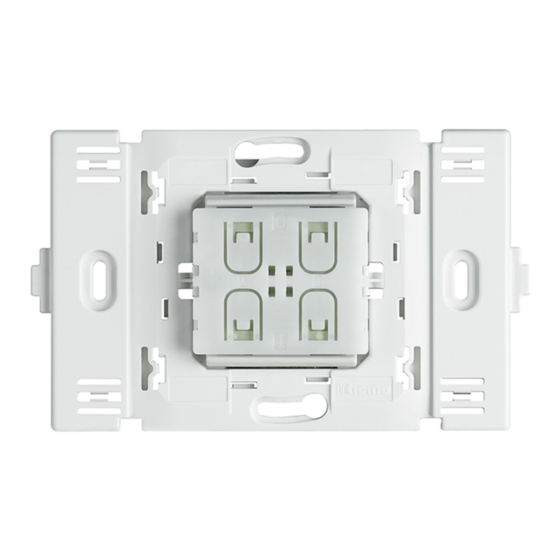
COMANDO RADIO L4572SB
Questo dispositivo permette di pilotare, attraverso l'interfaccia ricevente art. L/N/NT4575SB, l'impianto My Home.
Il comando non necessita di scatola da incasso in quanto può essere installato a parete mediante nastro biadesivo (a corredo) o
con normali tasselli ad espansione, non richiedendo quindi opere murarie.
INTERFACCIA RICEVENTE L/N/NT4575SB
L'interfaccia ricevente consente al comando radio L4572SB di pilotare l'impianto My Home.
Indicatore
luminoso,
LED
Pulsante a spillo
CONFIGURAZIONE DELL'INTERFACCIA RICEVENTE
Per poter utilizzare comando radio ed interfaccia ricevente, è necessario eseguire, anzitutto, le operazioni di configurazione
di quest'ultima e, successivamente, quelle di programmazione.
A
PL1
M1
PL2
M2
SPE
L/N/NT4575SB
Per l'utilizzo con placche Living International staccare
le parti laterali evidenziate in grigio nella figura
Vista frontale
L4572SB
L4572SB
L/N/NT4575SB
A
ambiente
punto luce 1
PL1
(punto fonico 1 solo per diffusione sonora SPE=8)
M1
modalità 1
PL2
punto luce 2
M2
modalità 2
SPE
speciale
Istruzioni d'uso
Instructions for use
Vista posteriore
07/07-01 PC
1
2
3
Advertisement

Summary of Contents for Bticino L4572SB
- Page 1 Il comando non necessita di scatola da incasso in quanto può essere installato a parete mediante nastro biadesivo (a corredo) o con normali tasselli ad espansione, non richiedendo quindi opere murarie. INTERFACCIA RICEVENTE L/N/NT4575SB L’interfaccia ricevente consente al comando radio L4572SB di pilotare l’impianto My Home. Indicatore luminoso,...
- Page 2 È possibile associare ad ogni singola interfaccia ricevente fino ad un massimo di 24 funzioni (quindi ad ogni interfaccia possono essere associati fino a 12 comandi radio L4572SB). L’associazione tra la funzione desiderata e la coppia di tasti viene effettuata attraverso la procedura di seguito descritta.
- Page 3 MODALITÀ STANDARD AUTOMAZIONE - Configuratore SPE=1 CONFIGURAZIONE Questa modalità di funzionamento permette di implementare le funzioni standard di automazione (ad esempio controllo di luci e tapparelle). La modalità M2 si riferisce La modalità M1 si riferisce alla coppia di tasti 2-4 alla coppia di tasti 1-3 Configurazioni modalità...
- Page 4 Tasto3 Scenario 16 Tasto4 Dopo aver configurato l’interfaccia, i quattro scenari associati al comando L4572SB possono essere richiamati anche da altri comandi dello stesso tipo (fino ad un massimo di 128 comandi). PROGRAMMAZIONE Per programmare uno scenario, la procedura è la seguente: 1) Il modulo scenari deve essere in configurazione con autoapprendimento abilitato (premere il tasto di autoapprendimento sul modulo scenari in modo che il relativo LED sia verde).
- Page 5 I configuratori PL2 e M2 devono essere 0. PROGRAMMAZIONE Per associare un comando radio art. L4572SB all’interfaccia L/N/NT4575SB, la procedura è la seguente: 1) Premere il pulsante a spillo sull’interfaccia per almeno 3 secondi: il LED rosso si accende fisso; rilasciare il tasto.
- Page 6 A e PL1 (se M1=3) oppure A e PL2 (se M2=3) sono l’indirizzo (due cifre) corrispondente al posto interno da cui si comandano le luci scale. Esempio di configurazione: Configurazione interfaccia Comando radio L4572SB L/N/NT4575SB Posto esterno 22 Luci scale 26...
-
Page 7: Dichiarazione Ce Di Conformità
Temperatura di funzionamento: 0°C ÷ +40°C DICHIARAZIONE CE DI CONFORMITÀ L’articolo: L4572SB è conforme ai requisiti essenziali della direttiva 1999/5/CE, in quanto rispetta le seguenti norme: ETSI EN 300 220-3 ETSI EN301 489-3 Anno di approvazione della marcatura CE secondo la direttiva indicata: 2005... - Page 8 The control does not need a flush-mounted box because it can be installed on the wall using two-sided adhesive tape (supplied), thus not requiring making holes in the wall, or with normal rawlplugs. RECEIVING INTERFACE L/N/NT457SB The radio interface lets the radio control L4572SB control the My Home system. Luminous indicator,...
-
Page 9: Sound System
- Reset. Both keys of the pair perform the same function. Up to 24 functions can be associated with each receiving interface (i.e. up to 12 radio controls L4572SB can be associated with each interface). The function required and the key pair are associated by means of the procedure described below. - Page 10 STANDARD AUTOMATION MODE - Configurator SPE=1 CONFIGURATION This mode of operation can implement the standard automation functions (e.g. control lights and rolling shutters). Mode M1 refers to pair Mode M1 refers to pair of keys 2-4 of keys 1-3 Mode configurations (M1, M2): a) M= —...
- Page 11 Key 3 Scenario 16 Key 4 After configuring the interface the four scenarios associated with remote control L4572SB can also be called by other remote controls of the same type (up to a maximum of 128 commands). PROGRAMMING To program a scenario, proceed as follows: 1) The scenario module must be in configuration with self-learning enabled (press the self-learning key so that its LED is green).
- Page 12 Configurators PL2 and M2 must be 0. PROGRAMMING To associate a radio control item L4572SB with interface L/N/NT4575SB, proceed as follows: 1) Press the pin pushbutton on the interface for at least 3 seconds: the red LED shines steadily. Release the key.
- Page 13 A and PL1 (if M1=3) and/or A and PL2 (if M2=3) are the address (two digits) corresponding to the handset which will control the staircase lights. Example of configuration: Radio control L4572SB Interface L/N/NT4575SB configuration Staircase lights 26 Entrance panel 22...
-
Page 14: Ce Declaration Of Conformity
Operating temperature: 0°C - +40°C CE DECLARATION OF CONFORMITY Item L4572SB conforms to the essential requirements of directive 1999/5/CE, because it respects the following standards: ETSI EN 300 220-3 ETSI EN301 489-3 Year of approval of the CE marking according to the directive indicated: 2005...
Need help?
Do you have a question about the L4572SB and is the answer not in the manual?
Questions and answers