Table of Contents
Advertisement
Available languages
Available languages
Quick Links
Bedienungsanleitung
DE
EN
PC 100 LCD CNC
Plasma Schneidinverter / Plasma Cutting Inverter
IMPORTANT: Read this Owner's Manual Completely before attempting to use this
equipment. Save this manual and keep it handy for quick reference. Pay particular
attention to the safety instructions we have provided for your protection. Contact your
distributor if you do not fully understand this manual.
User Manual
1.0004.0788-E
V1.3.22
Advertisement
Chapters
Table of Contents
Troubleshooting

Summary of Contents for MK Welding PC 100 LCD CNC
- Page 1 Bedienungsanleitung User Manual PC 100 LCD CNC Plasma Schneidinverter / Plasma Cutting Inverter 1.0004.0788-E V1.3.22 IMPORTANT: Read this Owner’s Manual Completely before attempting to use this equipment. Save this manual and keep it handy for quick reference. Pay particular attention to the safety instructions we have provided for your protection. Contact your...
-
Page 2: Table Of Contents
Inhaltsverzeichnis 1. ALLGEMEINES 2. SICHERHEITSANWEISUNG 3. BETRIEBSBEDINGUNGEN UND ARBEITSUMGEBUNG 4. TECHNISCHE DATEN 5. EINSCHALTDAUER 6. GERÄTE ÜBERSICHT LCD Ü BERSICHT EHLER ELDUNGEN YSTEM ENÜ YSTEM PRACHE ISPLAY ELLIGKEIT OFTWARE NFORMATION ISPLAY ELLIGKEIT 7. SCHNEIDEN INWEIS ICHTIGE RENNERFÜHRUNG 8. CNC SCHNITTSTELLE CNC B UCHSE 9. - Page 3 Copyright © 2020 MK Trade GmbH, Wies, Österreich. Die Inhalte dieser Bedienungsanleitung sind alleiniges Eigentum der Firma MK Trade GmbH. Eine Weitergabe sowie Vervielfältigung dieses Dokuments, Verwertung und Mitteilung seines Inhalts sind verboten, soweit nicht ausdrücklich gestattet. Zuwiderhandlungen verpflichten zu Schadenersatz. Technische Änderungen und Irrtümer vorbehalten.
-
Page 4: Allgemeines
1. Allgemeines Alle Personen, die mit diesem Gerät arbeiten, das Gerät bedienen, Wartungs- und oder Instandhaltungsarbeiten am Gerät durchführen, müssen - entsprechende Qualifikationen haben, - Kenntnisse vom Schweißen haben, - diese Bedienungsanleitung vollständig lesen, - die für Ihr Land gültigen Vorschriften beachten und einhalten. Bei Fehlbedienung, Missbrauch oder anderes besteht Gefahr für - Leib und Leben des Bedieners und Dritte, - Gerät und / oder Sachwerte. -
Page 5: Sicherheitsanweisung
2. Sicherheitsanweisung Die Anlage ist ausschließlich für das Plasmaschneidverfahren bestimmt. Das Bedienungspersonal muss über die Sicherheitshinweise unterrichtet werden. Die Anlage darf unter keinen Umständen von ungeschultem Personal bedient werden. Reparaturen im elektrischen Bereich dürfen nur von Elektrofachkräften ausgeführt werden. Bei Pflege-, Wartungs- und Reparaturarbeiten sowie vor Öffnen des Gehäuses immer Netzstecker ziehen. - Page 6 Da der Bediener bei unsachgemäßem Gebrauch bzw. einem einfachen Defekt in Berührung kommen könnte, gelten erweiterte Sicherheitsmaßnahmen. Handschuhe und Schuhe sind zu tragen, die ausreichende Isolierung bieten. Die gesamte Kleidung ist trocken zu halten. Erhöhte Vorsicht gilt in einer Umgebung mit hoher Feuchtigkeit! Alle an der Anlage angeschlossenen elektrischen Leitungen sind auf einwandfreien Zustand zu überprüfen.
- Page 7 Entstehung von Rauchgasen bzw. toxischen Dämpfen kann zu Sauerstoffmangel in der Atemluft führen. Immer für ausreichend Frischluft sorgen! Gasflaschen stehen unter hohem Druck und stellen eine Gefahren- Quelle dar. Der richtige Umgang mit ihnen ist unbedingt beim Gaslieferanten zu erfragen. Beispielsweise müssen die Flaschen auf jeden Fall vor direkter Sonneneinstrahlung, vor offenem Feuer und starken Temperaturschwankungen, z.
- Page 8 8. Folgen sie den Betriebsregeln beim betätigen der Schalter und bei Justierungen. 9.Tragen sie beim Schneiden Schutzkleidung. Dies beinhaltet: ein langärmeliges T-Shirt / Lederärmel, Schutzschürze ohne Taschen, lange schützende Hosen, Arbeitsschuhe und Schutzbrille. Wenn sie mit heißem Material arbeiten, sollten sie Schutzhandschuhe tragen. Auch für Helfer gelten die gleichen Schutzmaßnahmen wie für Sie.
-
Page 9: Betriebsbedingungen Und Arbeitsumgebung
Das vorliegende Gerät ist mit CE gekennzeichnet und entspricht den gültigen Normen (EMC 2014/30/EU & LVD 2014/35/EU, EN 60974-10:2014 +A1:2015 und CISPR 11:2019 +A1:2010 (Absatz 4.1, 4.2 Gruppe 2, Klasse A), EN60974:2012). Parameter PC 100 LCD CNC Eingangsspannung (V) 3-400V ±10%, 50 / 60 Hz Netzsicherung Träge (A) Max. -
Page 10: Einschaltdauer
Frontplatte. In diesem Fall sollte die Maschine 10 - 15 Minuten lang nicht schweißen, um sich mit dem Lüfterlauf abzukühlen. Bei erneutem Betrieb der Maschine sollte der Schweißausgangsstrom oder der Arbeitszyklus reduziert werden. I (A) PC 100 LCD CNC 120A 100A 100%... -
Page 11: Geräte Übersicht
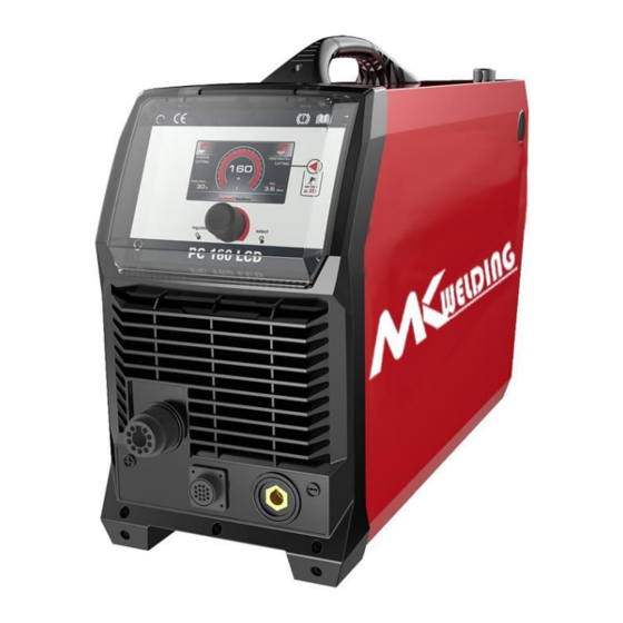
6. Geräte Übersicht Bild 1 Brenner Zentral Anschluss CNC Anschlussbuchse Masseklemme Kondenswasser Ablassschraube Druckmanometer Eingang Eingangsdruck Einstellschraube Druckluft Eingang Netzkabel Netzschalter... -
Page 12: Lcd Übersicht
LCD Übersicht Bild 2 Vollmaterial Schneiden Modus Anzeige für Aktuellen Parameter Lochblech Schneiden Modus Luft Nachlaufzeit Schneidstrom Einstellung Luftnachlaufzeit Einstellung Eingangsdruck Luft Auswahl Modus Parameter Einstellknopf Luft Test Um einen Lufttest durchzuführen Drücken Sie „8“ (Bild 2 / Seite 11). Am lange die Taste Display erscheint das Bild links. -
Page 13: Fehler Meldungen
Fehler Meldungen Luftfehler, erscheint wenn zu wenig bzw. keine Druckluft vorhanden ist. Brenner Fehler, erscheint wenn kein Brenner bzw. der Sicherheitskontakt am Brenner unterbrochen ist. Thermische Überhitzung, erscheint wenn das Gerät überhitzt. Netz Phase Fehlt, erscheint wenn mindestens 1 Netzphase fehlt bzw. eine Phase wenn nicht alle 3 Phasen am Gerät Anliegen. -
Page 14: Display Helligkeit
System Sprache Drücken Sie die Taste „8“ (Bild 2 / Seite 11) bis der Parameter „1“ (System Sprache) erscheint wie im Bild neben. Durch Drehen des Einstellknopfes „9“ (Bild 2 / Seite 11) kann die Sprache eingestellt werden und durch drücken des Einstellknopfes „9“... -
Page 15: Schneiden
7. Schneiden - Schließen Sie das Netzkabel an (die Eingangsspannung finden Sie in der Rubrik Technische Daten und am Typenschild des Gerätes) - Verbinden Sie den Druckluft Eingang mit der Luftversorgungsanlage. - Schließen Sie das Massekabel und den Brenner korrekt am Gerät an. - Schalten Sie das Gerät ein und stellen Sie die Druckluft auf ca. -
Page 16: Richtige Brennerführung
Unterseite eine große Schlakenbildung. Bei Korrekter Geschwindigkeit erhalten Sie einen sauberen Schnitt. 8. CNC Schnittstelle Der PC 100 LCD CNC ist mit einem optionalen, werkseitig installierten Spannungsteiler mit vier Spannungen ausgestattet, der für einen sicheren Anschluss ohne Werkzeug ausgelegt ist. - Page 17 Beachten Sie die folgende Tabelle, wenn Sie den Plasmaschneider mit einem Maschinenschnittstellenkabel an einen Brennerhöhenregler (THC) oder einen CNC-Regler anschließen. Signal Beschreibung Stecker PIN Potentialfreier Kontakt, Kontakt offen ist Standby, geschlossen Startsignal Eingang ist Schneidstrom Aktiv 8、9 (Brennerstart) 18 VDC Leerlaufspannung an den Klemmen.
-
Page 18: Fehlerursachen - Behebung
9. Fehlerursachen - Behebung Fehler Mögliche Ursache Behebung Netz angeschlossen und Netzsicherung hat ausgelöst Netzsicherung prüfen Netzschalter auf „I“ – Netzanschluss unterbrochen Netzanschluss prüfen Kontrollleuchte Netz leuchtet nicht Alarmleuchte leuchtet Gerät ist Überhitzt Der Alarm wird nach Ablauf der Lüfterkühlung freigegeben und Sie können das Gerät neu starten Überstrom Die Alarmleuchte leuchtet... - Page 19 Monatlich - Das Gerät mit trockene Luft Ausblasen und Reinigen. - Isolationsmessung und Service des Gerätes. Bei nicht Jährlich Durchführung erlischt die Garantie/ Gewährleistung. (Durchführung nur durch einem vom Hersteller autorisiertem Fachpersonal) Jegliche Arbeiten im und am Gerät, Änderungen usw. dürfen nur durch ein Autorisiertes Fachpersonal durchgeführt werden, ansonsten kann es zum Verfall der Zulassung führen und auch zum Erlöschen der Garantie / Gewährleistung.
-
Page 20: Schematischer Schaltplan
11. Schematischer Schaltplan... -
Page 21: Ersatzteile Brenner
11. Ersatzteile Brenner Luftmenge: ca. 200l/min Arbeitsdruck: ca. 4,5 – 5 Bar (am Düsenausgang) Luft Nachlaufzeit: 90sec. - Page 23 CONTENT §1 SAFETY ........................1 §1.1 S YMBOLS XPLANATION §1.2 M ACHINE PERATING WARNINGS §1.3 EMC DEVICE CLASSIFICATION §1.4 EMC MEASURE §1.5 W ARNING LABEL §2 OVERVIEW ........................ 10 §2.1 F EATURES §2.2 T ECHNICAL §2.3 W ORKING RINCIPLE §2.4 D UTY CYCLE AND HEAT §2.5 V...
- Page 24 Copyright © 2020 MK Trade GmbH, Wies, Austria The contents of these User Manual are the sole property of the company MK Trade GmbH. Passing on as well as copying of this document, the use and distribution of its content are prohibited if not explicitly permitted.
-
Page 25: Safety
§1 Safety Welding and cutting equipment can be dangerous to both the operator and people in or near the surrounding working area, if the equipment is not correctly operated. Equipment must only be used under the strict and comprehensive observance of all relevant safety regulations. - Page 26 work circuit is electrically live whenever the output is on. The input power circuit and internal machine circuits are also live when power is on. In Mig/Mag welding, the wire, drive rollers, wire feed housing, and all metal parts touching the welding wire are electrically live. Incorrectly installed or improperly grounded equipment is dangerous.
- Page 27 Welding produces fumes and gases. Breathing these fumes and gases can be hazardous to your health. Do not breathe the smoke and gas generated whilst welding or cutting, keep your head out of the fumes. Use enough ventilation and/or exhaust at the arc to keep fumes and gases away from the breathing zone.
- Page 28 SELF-PROTECTION Keep all equipment safety guards, covers and devices in position and in good repair. Keep hands, hair, clothing and tools away from V-belts, gears, fans and all other moving parts when starting, operating or repairing equipment. Do not put your hands near the engine fan. Do not attempt to override the governor or idler by pushing on the throttle control rods while the engine is running.
- Page 29 inside. They can cause an explosion even though they have been “cleaned”. Vent hollow castings or containers before heating, cutting or welding. They may explode. Sparks and spatter are thrown from the welding arc. Wear oil free protective garments such as leather gloves, heavy shirt, cuff less trousers, high shoes and a cap over your hair.
- Page 30 Gas Cylinders. Shielding gas cylinders contain gas under high pressure. If damaged, a cylinder can explode. Because gas cylinders are normally part of the welding process, be sure to treat them carefully. CYLINDERS can explode if damaged. Protect gas cylinders from excessive heat, mechanical shocks, physical damage, slag, open flames sparks, and arcs.
-
Page 31: Emc Device Classification
All cables should be put away and far from the operator. Never coil the power cable around your body. Make sure welding machine and power cable to be far away from the operator as far as possible according to the actual circumstance. ... -
Page 32: Emc Measure
hanker welding machines belong to Class A. §1.4 EMC measure In the special situation, The specified area may be affected, the standard of radiation limit value has been complied with (eg: The device, which is easy effected by electromagnetism, is used at the installation location, or there is radio or TV near the installation location). -
Page 33: Warning Label
§1.5 Warning label The device with a warning label. Do not remove、destroy or cover this label. These warnings are intended to avoid incorrect device operations that could result in serious personal injury or property damage. -
Page 34: Overview
§2 Overview §2.1 Features IGBT module inverter technology for smooth, stable output, increased reliability . Microprocessor control system for superior & dynamic arc characteristics. CNC interface connection. Euro connect torch system with safe & robust connection to machine. -
Page 35: Technical Data
§2.2 Technical Data dels PC 120 LCD PC 100 LCD Parameters 3-380V/400V±10% Rated input voltage(V) 50/60Hz Rated input current(A) Rated input power(KW) 10.4 Cutting current adjustment 20~120 20~100 range (A) No-load voltage (V) 420V 60% 120A Duty cycle(40℃ 10minutes) 100% 100A 100% 93A The max. -
Page 36: Working Principle
§2.3 Working Principle The working principle of CUT series of Air Plasma Cutting machines is shown as the following figure. Three-phase 380V line frequency (50/60 Hz) AC is rectified into DC, then it is converted to medium frequency AC (about 20KHz) by inverter device (discrete IGBT), after reducing voltage by medium transformer (the main transformer) and rectified by medium frequency rectifier (fast recovery diode), and is outputted by inductance filtering. -
Page 37: Volt -Ampere Characteristic
§2.5 Volt-Ampere Characteristic CUT series of Air Plasma Cutting machines has excellent volt-ampere characteristic. Referring to the following graph. The relation between the rated loading voltage U welding current I is as follows: When I ≤600A,U =80+0. 4 I (V);When 165A<I ≤500A,U =130+0. - Page 38 (1) Plasma Torch Euro/ Central Connector. (2) CNC Interface Connection (3) Earth Lead Connection Socket. (4) Air Filter Condensate Drain Tube. (5) Air Pressure Regulator Outlet Pressure Gauge. (6) Air Pressure Regulator Knob. (7) Compressed Air Inlet. (8) Input Power Cable. (9) Power Switch: Turn on or off the power source.
- Page 39 Long press button(8) for 2 seconds to enter the check gas, and the display screen will display the above interface When positioned as ‘set’ compressed air control valve is open continuously. This is useful for testing and setting the air pressure without having to activate the trigger circuit.
- Page 40 indicator lamp goes out. May also trigger if machine experiences an internal power circuit failure. Phase loss Error Display (4) System setup interface Press the knob(9) for 3 seconds to enter the setting interface, Switch(8) the setting interface by pressing the button and set parameters by the knob(9) Language selection interface (1) Brightness adjustment interface (2) Language selection interface (3)
- Page 41 Pilot Arc System CUT series of Air Plasma Cutting machines use a pilotarc system to establish the main cutting arc. A pilot arc system is a circuit where the return is back through the torch head and cable. This means it can create a small arc with some cutting power without making any electrical connection with the main machine earth.
-
Page 42: Installation & Operation
be replaced. Swirl Ring/Retaining Cap: These should be replaced if broken, chipped, cracked or badly heat damaged. Tips and electrodes: These should wear reasonably evenly and it is normal practice to replace them both together. If a new tip is inserted with a worn electrode the tip will wear much more quickly than if the electrode was also replaced at that same time. - Page 43 (FAD) at 75psi pressure. This normally means the compressor must be a belt drive model or if a direct drive it must have a motor power of 2.5HP or greater. The air must be dry and free of oil and moisture (normally a symptom of older, worn out compressors).
- Page 44 tip-to-work (standoff) distance. 5) When ending a cut, the torch switch should be released and lifted off the work piece just before the end of the cut to minimize double-arcing which can damage the tip. This is to prevent the high frequency arc starting from reigniting after cutting arc extinguishes.
- Page 45 voltage divider that is designed to be safely connected without tools. The built-in voltage divider provides a scaled down arc voltage of 20:1, 30:1, 40:1, and 50:1 (maximum output of 18 V). An optional receptacle on the rear of the power supply provides access to the scaled down arc voltage and signals for arc transfer and plasma start.
- Page 46 Refer to the following table when connecting the CUT system to a torch height controller or CNC controller with a machine interface cable. signal type Instruction connector Cable ends socket Normally open. 18 VDC open circuit Start (start voltage at START (yellow)...
-
Page 47: Plasma Cutting Guide
§3.3 Plasma Cutting Guide §3.3.1 Cutting Guide Effect of Cutting Speed Piercing Technique NOTE: Keep moving while cutting. Cut at a steady speed without pausing. Maintain the cutting speed so that the arc lag is 10°to 20°behind the travel direction. Use a 5°- 15° leading angle in the direction of the cut. - Page 48 accomplishing the pierce. 2. Grate Cutting - For rapid restarts, such as grate or heavy mesh cutting, do not release the torch switch. This avoids the 2 second pref-flow portion of the cutting cycle. 3. Edge Starting – For edge starts, hold the torch perpendicular work piece with the front of the tip near (not touching) the edge of the work piece at the...
- Page 49 before moving on. Adjust drag speed as desired/ required. 5. Direction of Cut - The plasma gas stream swirls as it leaves the torch to maintain a smooth column of gas. This swirl effect results in one side of a cut being more square than the other.
-
Page 50: Troubleshooting
‘Top dross’ is normally very easy to remove and can often be wiped off with a welding glove. ‘Slow speed dross’ is normally present on the bottom edge of the plate. It can vary from a light to heavy bead, but does not adhere tightly to the cut edge, and can be easily scraped off. -
Page 51: Operation Environment
4. Worn torch parts 4. Inspect repair or replace worn parts Install air drier or additional Water in the air supply sputters/flares filtration 1. Material too thick, increase angle to prevent blow back into torch tip 2. Do not operate HF ARC starting for more than 3 seconds –... -
Page 52: Maintenance & Troubleshooting
▲Before operation, none concerned people should not be around the working area and especially children. Do not watch the arc in unprotected eyes. ▲ Ensure good ventilation of the machine to improve Duty Cycle. ▲ Turn off the engine when the operation finished for energy consumption efficiency. ▲When power switch shuts off protectively because of failure. -
Page 55: Troubleshooting Principle
§4.2 Troubleshooting Principle WARNING There are extremely dangerous voltage and power levels present inside this unit. Do not attempt to diagnose or repair unless you have had training in power electronics measurement and troubleshooting techniques. A. Power lamp and temperature lamp on. 1. - Page 56 4. Faulty Torch, return for repair or have qualified technician repair. D. Low cutting output 1. Incorrect setting of CURRENT (A) control, check and adjust to proper setting. 2. Faulty components in unit, return for repair or have qualified technician repair. E.
-
Page 57: Electrical Schematic Drawing
§4.3 Electrical schematic drawing... - Page 58 Produkt Marke: MK Welding Produkt Gruppe: Schneiden Produkt Type: Plasmaschneider Bezeichnung des Produktes: PC 100 LCD CNC Seriennummer*: 1.0004.0788-E _____________________ Baujahr*: 20_________ (Ersichtlich anhand der Seriennummer) * anhand des Typenschildes am Gerät Auszufüllen Das oben genannte Erzeugnis stimmt mit den Vorschriften folgender Europäischen Richtlinien überein:...
Need help?
Do you have a question about the PC 100 LCD CNC and is the answer not in the manual?
Questions and answers