
Related Manuals for RHEONICS SR

Summary of Contents for RHEONICS SR
- Page 1 PROFINET Field Device Specification: Rheonics, SME Covers sensor Types: SR, SRV, SRD, DVP, DVM...
- Page 2 Rheonics. The information contained in this manual is subject to change without notice. TRADEMARKS Rheonics is a trademark of Rheonics, Inc. Other product and company names listed in this manual are trademarks or trade names of their respective manufacturers.
-
Page 3: Table Of Contents
Operators Manual Contents Contents 1 Before you begin ................... 4 2 Which gds file do i need? ............... 5 3 Product overview .................. 6 4 Profinet Installation ................7 5 Getting started ..................8 6 Installation process ................11 7 Device configuration settings .............. 15 8 Sensor status and parameter status ............ -
Page 4: Before You Begin
PNET -OP-2022 Before you begin Before you begin About the manual This manual provides information on Profinet support on Rheonics devices. This document specifies all the device-specific features and documents PROFINET Protocol implementation details. Important Instructions This manual assumes that the following conditions apply: •... -
Page 5: Which Gds File Do I Need
Which GDS file do I need? Which GDS file do I need? Rheonics GDS File provides the configuration information, parameters, modules, diagnostic and vendor and device identification; to be used by the controller. For up-to-date information, please check the page: https://support.rheonics.com/support/solutions/articles/81000401423-profinet-... -
Page 6: Product Overview
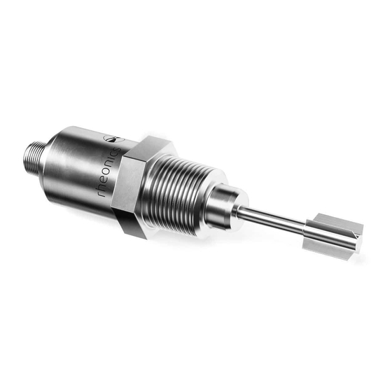
Figure 1. SME sensor electronics unit. Process Interface The SME is compatible with various Rheonics instruments. This includes Type: SR (SRV & SRD), Type: DV (DVP, DVM) and other instruments using the SME electronics from Rheonics. Figure 2. Rheonics Sensor for Viscosity and density measurements. -
Page 7: Profinet Installation
PNET Operators Manual Chapter 4 PNET -OP-2022 Profinet Installation Profinet Installation Instrument overview: Figure 3. SME-DRM Diagram. Ethernet PIN assignment PROFINET Pin Number Wire Color Description RJ45 Connector Receptacle Yellow Transmit+ Orange Transmit- White Receive+ Not Used Not Used Blue Receive- Not Used Not Used... -
Page 8: Getting Started
• Ethernet Switch System Connections Connect Rheonics sensor, PLC, and PC (with RCP software installed) with an Ethernet Cable. We recommend using an Ethernet Switch. Connect SME to the PC running RCP to configure the SME. Figure 4. Communication diagram for rheonics sensor-PLC and PC. - Page 9 PNET -OP-2022 Getting started Configure Rheonics SME Open RCP software on the connected PC, connect to the SME using USB and configure the SME to use DHCP. Make sure it has a valid IP address. Figure 5 shows a standard configuration that can be used for the correct performance of the system.
- Page 10 PNET Operators Manual Chapter 5 PNET -OP-2022 Getting started Figure 6. RCP showing Ethernet setting - Disable DHCP, this will allow use of static IP Address. 5.3.4 Fill all the parameters for the Profinet, remember to use valid values. Figure 7. Update SME with Ethernet parameters.
-
Page 11: Installation Process
6.2.1 Select [Manage general station description files (GSD)] in the [Options] menu. Figure 8. Screenshot of GSD file upload in TIA portal. 6.2.2 Select the file: GSDML-V2.4-Rheonics-SMET-20220321.xml, load and install this file. Figure 9. Adding GSDML file in TIA portal. - Page 12 Figure 10. Select device configuration from device tree. From the [Hardware Catalog] 6.4.1 Choose the appropriate Rheonics sensor. Figure 11. Selecting appropriate device from Hardware Catalog. Select “Rheonics SMET” and add the device to your project. 6.4.2 Figure 12.Rheonics SMET device in the I/O device tree.
- Page 13 Chapter 6 PNET -OP-2022 Installation process Rheonics sensor will appear in topology view. Figure 13. Rheonics sensor as it appears in Topology View. Connect the Rheonics sensor SMET to the PLC 6.6.1 Drag & drop the connection. Figure 14. Screenshot showing Module Definition-Module Info.
- Page 14 Chapter 6 PNET -OP-2022 Installation process Once PLC and SMET are connected you will find green wire that connects both PLC controller and rheonics sensor. Figure 15. Establishing Profinet network by connecting Rheonics SMET to PLC in TIA portal software.
-
Page 15: Device Configuration Settings
Rheonics device provides 2 modules “Diagnostics_1” and “Device Parameters_1”. Figure 16. Device overview Controller Address. Diagnostics_1 7.2.1 This module covers data that is useful for Rheonics support team to help customers diagnose any issues. - Page 16 PNET Operators Manual Chapter 7 PNET -OP-2022 Device configuration settings Figure 17. Diagnostic module. Device Parameters_1 This module covers the 22 parameters available for the SMET, as well the sensor status parameter. 7.3.1 Define tags in the PLC table based in the information from the GSD file. Figure 18.
- Page 17 PNET Operators Manual Chapter 7 PNET -OP-2022 Device configuration settings Figure 19. Data monitor from SMET showing the measured data in both the TIA portal and RCP.
-
Page 18: Sensor Status And Parameter Status
Sensor status and parameter status Sensor status and parameter status All rheonics sensors (SRV, SRD, DVP, DVM) for inline viscosity and density monitoring have inbuilt status. These status bits can be used over digital communication channels to understand when the sensor is operating correctly and when there is an issue. - Page 19 No result is yet available. Example: No measurement has been taken yet. The algorithm requires a run-in time Bit 5 0x0020 Internal error Internal error - Report to Rheonics Bit 6 0x0040 Calibration Diagnostics Error Bit 7 0x0080 Further use...
- Page 20 PNET Operators Manual Chapter 8 PNET -OP-2022 Sensor status and parameter status How to read sensor status? Sensor status is a WORD data type, these status bits can be used over digital communication channels to understand when the sensor is operating correctly and when there is an issue. Figure 20.
- Page 21 Chapter 8 PNET -OP-2022 Sensor status and parameter status For each of the 22 parameters from Rheonics sensor, 5 components are provided: Scaled value, unscaled value, parameter status, private status and unit. For up-to-date parameters information, please check the page: https://support.rheonics.com/support/solutions/articles/81000393235-...
-
Page 22: Cyclic Input Data
PNET Operators Manual Chapter 9 PNET -OP-2022 Cyclic input data Cyclic input data Rheonics sensors can be used for reading data. Diagnostics information Name Data Type Comment Input Voltage Float32 Power source to the Integer32 Diagnostics Integer32 Diagnostics Integer32 Diagnostics... - Page 23 PNET Operators Manual Chapter 9 PNET -OP-2022 Cyclic input data Parameters Name Data Type Comment Sensor Status Unsigned16 This parameter is Word data type. Format should be little endian. Parameter 0 Viscosity Float32 Median of last 5 viscosity Median value measurements Parameter 0 Viscosity Float32...
- Page 24 PNET Operators Manual Chapter 9 PNET -OP-2022 Cyclic input data Parameter 3 Kinematic Unsigned16 Diagnostics Viscosity private status Parameter 3 Kinematic Unsigned8 Unit for parameter 3, refer to Table Viscosity unit Parameter 4 density Float32 Average of density measurements average value Parameter 4 density Float32 Average of density measurement...
- Page 25 PNET Operators Manual Chapter 9 PNET -OP-2022 Cyclic input data Parameter 8 resonant Float32 Instantaneous value of frequency frequency (Hz) value from the measurement Parameter 8 resonant Float32 Instantaneous value of frequency frequency (Hz) raw value from the measurement prior to applying the user calibration Parameter 8 resonant Unsigned16...
- Page 26 PNET Operators Manual Chapter 9 PNET -OP-2022 Cyclic input data Parameter 11 Coil Unsigned16 Diagnostic temperature private status Parameter 11 Coil Unsigned8 Unit for parameter 11, refer to Table temperature unit Parameter 12 viscosity Float32 This parameter provides the viscosity median and last good value median measurement value and if there is any error in memory last...
- Page 27 PNET Operators Manual Chapter 9 PNET -OP-2022 Cyclic input data Parameter 14 unit Unsigned8 Unit for parameter 14, refer to Table Parameter 15 Float32 Displays of mapped value from Modbus register 514 value Parameter 15 Float32 Displays of mapped value from Modbus register 514 value prior to applying the user calibration Parameter 15...
- Page 28 PNET Operators Manual Chapter 9 PNET -OP-2022 Cyclic input data Parameter 18 Unsigned16 Diagnostic Parameter 18 Unsigned8 Unit for parameter 18, refer to Table Parameter 19 Calculated Float32 Mathematical model for viscosity parameter from viscosity from the measurement model value Parameter 19 Calculated Float32 Mathematical model for viscosity...
- Page 29 PNET Operators Manual Chapter 9 PNET -OP-2022 Cyclic input data concentration model private status Parameter 21 Calculated Unsigned8 Unit for parameter 21, refer to Table parameter from concentration model unit Parameter 22 Sensor Float32 Sensor status measurement cleanliness ratio value Parameter 22 Sensor Float32 Sensor status measurement prior to...
-
Page 30: Units Table
PNET Operators Manual Chapter 10 PNET -OP-2022 Units table Units table Unit Unit Unit Unit Index Display Index Display %wt/v mPa.s %v/v %vol Pa.s Poise Reyn sccm Tref %Vol mol/m μ alcohol η ethanol ν °C °F °P °K XX°Y g/cc Kg/m lb/ft... -
Page 31: Troubleshooting
Wrong readings for each parameter 1. Verify each parameter is correctly mapped, some bytes are swapped Sensor Status does not match any bit from the 1. Sensor status byte is swapped sensor status table https://support.rheonics.com/support/solutions/articles/81000401486- profinet-troubleshooting... - Page 32 PNET Operators Manual Chapter 11 PNET -OP-2022 Troubleshooting • Contact RHEONICS support desk support@rheonics.com https://support.rheonics.com https://support.rheonics.com/support/home...
-
Page 33: Notes/Errata
PNET Operators Manual Chapter 12 PNET -OP-2022 Notes/Errata Notes/Errata Contact Rheonics support for customization of system settings. Notes... - Page 34 Tel: +1 713 364 5427 Website: https://rheonics.com ©2021 Rheonics, Inc. All rights reserved. Support Portal: https://support.rheonics.com The Rheonics logo is a trademark and service mark of Support E-Mail: support@rheonics.com Rheonics Inc. Photographs, excerpts, trademarks, and Sales E-Mail: info@rheonics.com logos are not endorsements and are used only for representation under fair use copyright laws.
Need help?
Do you have a question about the SR and is the answer not in the manual?
Questions and answers