Table of Contents
Advertisement
Quick Links
Advertisement
Table of Contents

Related Manuals for VAN DER ENDE Envalve VK Series

Summary of Contents for VAN DER ENDE Envalve VK Series
- Page 1 Series VK, VKF and PVK Version 2.1 of October 2011...
-
Page 2: Preface
Van der Ende Pompen B.V. Maasambacht 4 2676CW Maasdijk Nederland Preface This installation manual is a manual for the installer or technician who is installing the Envalve. It is not a manual for the (end) user of the Envalve. If not entirely installed and connected, the Envalve has no real function and is therefore classified as a machine which cannot function independently (or unfinished machine , later on this is called just machine ). -
Page 3: Table Of Contents
Van der Ende Pompen B.V. Maasambacht 4 2676CW Maasdijk Nederland List of contents Preface ......................... 2 List of contents ......................3 1. Identification ....................... 4 1.1 General information ................... 4 1.1.1 Description of the machine ................4 1.1.2. Specifications ....................5 1.2 Schematic picture of the machine ................ -
Page 4: Identification
Van der Ende Pompen B.V. Maasambacht 4 2676CW Maasdijk Nederland 1. Identification In this chapter some general information about the machine is listed. The purpose of this chapter is to state the boundaries of the machine, the global functioning and possible applications of the machine. -
Page 5: Specifications
Van der Ende Pompen B.V. Maasambacht 4 2676CW Maasdijk Nederland 1.1.2. Specifications Type Power 3.5 W Voltage 24 of 230 Vac Capacity 10 - 100 m / hour/valve Pressure max. 6 bar 20 - 63 Drive Electromotor Centra Honeywell VMM or VMK Table 1. -
Page 6: Schematic Picture Of The Machine
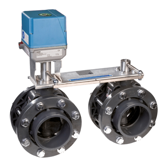
Van der Ende Pompen B.V. Maasambacht 4 2676CW Maasdijk Nederland 1.2 Schematic picture of the machine In this picture, the parts and components are numbered. Picture 1. Schematic picture of an Envalve. Note; the Envalve in the picture is a VKF, although other versions are not entirely the same, the main components and the functions of the components is the same. -
Page 7: Operation And Manual Control
Van der Ende Pompen B.V. Maasambacht 4 2676CW Maasdijk Nederland Name Drive Position indicator manual - auto control button Base plate Coupling Housing Paddle Secondary butterfly valve Collar Flange Primary butterfly valve (direct driven) Seal Connector shaft Coupling rod Table 4. Names of the main components. -
Page 8: Users
Van der Ende Pompen B.V. Maasambacht 4 2676CW Maasdijk Nederland 1.4 Users In general, there are no direct users of the Envalve, because it is operated remotely by a control panel or other (semi)automatic controller. Allowed users are at least 18 years and employed at the company at which the Envalve is installed, and who are designated to be competent and able to operate the Envalve. -
Page 9: Warranty
Van der Ende Pompen B.V. Maasambacht 4 2676CW Maasdijk Nederland Install the Envalve only if there is enough free space around it, a person must be able to operate the button man auto (c) safely. It must be impossible for a person to get stuck between the base plate and connector shaft or other objects. -
Page 10: Description
Van der Ende Pompen B.V. Maasambacht 4 2676CW Maasdijk Nederland 2. Description In this chapter the machine is described, it is the background information needed to work safely with the machine. 2.1 Working principle The Envalve regulates the flow by means of turning a paddle in a housing. By turning the paddle, the effective diameter of the pipe changes. -
Page 11: Safety Instructions
Van der Ende Pompen B.V. Maasambacht 4 2676CW Maasdijk Nederland 3. Safety instructions Read and understand this installation manual and take all the prescribed precautions before installing or connecting the Envalve! The Envalve may only be used for the applications the Envalve was designed for. -
Page 12: Installation
Van der Ende Pompen B.V. Maasambacht 4 2676CW Maasdijk Nederland 4. Installation 4.1 Mechanical For the correct installation of the Envalve, first fit all the piping without glue. When everything is correct in size and properly aligned, loosen the bolts or the nut and take the actual valve from between the collars. - Page 13 Van der Ende Pompen B.V. Maasambacht 4 2676CW Maasdijk Nederland When the valve is positioned correctly between the collars the flanges can be shoved over the collars and secured with the metal bolts and nuts (NW75 and larger) or the nut can be tightened (NW63 and smaller).
-
Page 14: Electric
Van der Ende Pompen B.V. Maasambacht 4 2676CW Maasdijk Nederland 4.2 Electric The valves must be electrically connected by professional and competent persons, look at the pictures in the annexes for help. VK series Remove the three screws from the lid of the drive;... -
Page 15: Commissioning
Van der Ende Pompen B.V. Maasambacht 4 2676CW Maasdijk Nederland 5. Commissioning Check whether the valve is installed correctly and the flanges or nut are secured. Check before filling the system with fluid again the functioning (manual and automatic). When the Envalve is set from manual to automatic (remote) operation, push against the connector shaft until a click is heard. -
Page 16: Errors
Van der Ende Pompen B.V. Maasambacht 4 2676CW Maasdijk Nederland 7. Errors Problem Cause Solution 1. Valve does not turn Control button man auto is set to manual Put the valve in the neutral position! Set the control button to auto and push against the connector shaft until a click is heard. -
Page 17: Declaration Of Conformity
Van der Ende Pompen B.V. Maasambacht 4 2676CW Maasdijk Nederland 8. Declaration of conformity EG-DECLARATION OF CONFORMITY (according to Annex II B of the Machinery Directive 2006/42/EG, for machinery which cannot function independently or machinery parts) Van der Ende Pompen B.V... -
Page 18: Annexes
Van der Ende Pompen B.V. Maasambacht 4 2676CW Maasdijk Nederland Annexes Electric schematics Declaration of conformity of components Installation manual Envalve series VK, VKF and PVK Page 18 of 23... -
Page 19: Electric Schematics
Van der Ende Pompen B.V. Maasambacht 4 2676CW Maasdijk Nederland Electric schematics VK series Picture 6, electric scheme VK series. Terminal 1 is the ground cable, when terminal 1 and 2 are connected to a power source, the valve will turn clockwise, when terminal 1 and 3 are connected to a power source, the valve will anticlockwise. - Page 20 Van der Ende Pompen B.V. Maasambacht 4 2676CW Maasdijk Nederland VKF series Picture 7, electric scheme VKF series. Terminal N1 is the ground cable, the control current runs through terminal 2 and/or 3. The earth cable must be connected to the terminal marked with the earth sign.
- Page 21 Van der Ende Pompen B.V. Maasambacht 4 2676CW Maasdijk Nederland PVK series Picture 8, electric scheme control valve PVK The flat plug (marked with a small earth sign) is the earth connection, by running a current from connection 1 to 2 (a steering current), the control valve will open and the Envalve will open. The control valve is monostable, so the control valve will close automatically (and the Envalve will return to its default position) when the steering current is removed.
-
Page 22: Declaration Of Conformity Of Components
Van der Ende Pompen B.V. Maasambacht 4 2676CW Maasdijk Nederland Declaration of conformity of components Installation manual Envalve series VK, VKF and PVK Page 22 of 23... - Page 23 Van der Ende Pompen B.V. Maasambacht 4 2676CW Maasdijk Nederland Installation manual Envalve series VK, VKF and PVK Page 23 of 23...
Need help?
Do you have a question about the Envalve VK Series and is the answer not in the manual?
Questions and answers