Table of Contents
Advertisement
Quick Links
Advertisement
Table of Contents

Summary of Contents for GEKKO GeVentor GEV019-100
- Page 1 GeVentor Ventilator GEV019-100 Instructions for Use Gekko Medical Pty Ltd...
- Page 2 Instructions for Use: GEV019-100 NOTE: Page 2...
-
Page 3: Table Of Contents
Instructions for Use: GEV019-100 Table of Contents Introduction ..................................5 Labels ....................................6 Safety Instructions ................................8 Safety Symbols ..................................8 Warnings and Contraindications ............................8 System Overview ................................11 Operating Concept ................................11 Device Description ................................13 Single Use Components ..............................15 Patient Breathing Circuit .............................. - Page 4 Instructions for Use: GEV019-100 10.1 Technical Specifications ..............................55 10.2 Electrical Classifications ..............................56 10.3 Ventilator Accuracy Testing .............................. 57 11 Accessories, Spare Parts and Consumables ........................59 12 Additional Service, Maintenance and Warnings........................ 60 13 Warranty and Manufacturer Contacts ..........................61 14 Glossary of Terms ................................
-
Page 5: Introduction
IFU Document Overview: This Instructions for Use (IFU) document contains important information for the installation, operation and maintenance of GeVentor GEV019-100 intended for use in clinical intensive care settings. Please read and understand its contents before installation and operation. Product Misuse: Gekko Medical Pty Ltd manufactures products to required standards and genuine parts have been designed and tested to ensure continued product quality and performance in use. -
Page 6: Labels
Instructions for Use: GEV019-100 Labels Front: The front labels of the GeVentor areas per the label given below. Patient circuit: On the side of the GeVentor, where the patient breathing circuit is connected, the label below is available. Page 6... - Page 7 Instructions for Use: GEV019-100 Warning: On the rear of the GeVentor, the label below is available. Page 7...
-
Page 8: Safety Instructions
The GeVentor must be inspected and maintained regularly as detailed in Section 8 (Maintenance and Cleaning) of this IFU document. It is recommended that servicing be performed by qualified service personnel. Gekko Medical Pty Ltd recommends a service contract is agreed upon, and that all parts used are genuine parts supplied by the manufacturer. - Page 9 Instructions for Use: GEV019-100 Connection to Electrical Supply Power: DANGER Risk of electrical shock. Device to be connected to earthed mains power outlet only. Before operating the GeVentor, adhere to instructions provided in Section 6 of this document. DANGER Risk of electrical shock. Device to be connected to earthed mains power outlet only.
- Page 10 Instructions for Use: GEV019-100 Interactions with Other Devices: CAUTION Other devices that may be connected to the GeVentor must comply with approved design, installation and operation requirements for use with the GeVentor. If in doubt, contact the manufacturer. Refer to Section 6.20 for more detail.
-
Page 11: System Overview
Instructions for Use: GEV019-100 System Overview 4.1 Operating Concept In principle, the operation of the lung comprises the Inspiration and Expiration of air from the lungs. To achieve the best outcome for the patient it is necessary to break down the operation into the component functions. Refer to the Process Flow Diagram for reference as per the description below. - Page 12 Instructions for Use: GEV019-100 Process Flow Diagram: R1 = Oxygen regulator 1, controls the pressure of the GeVentor Expiration Valve (GEV) which maintains pressure in the patient circuit above PEEP pressure. R2 = Oxygen supply regulator 2, controls Inspiration pressure to the FiO mixing valve.
-
Page 13: Device Description
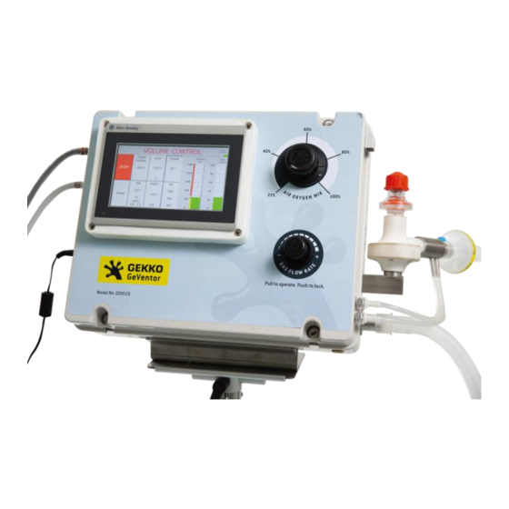
Instructions for Use: GEV019-100 4.2 Device Description Front Panel and User Interface: Air/Oxygen LCD Touch Screen Mixing Control Knob (HMI) Air Connection Port GeVentor Expiration Valve (GEV) Oxygen Gas Connection Port Expiration Hose Connection Port Power ON / OFF Switch Electrical Power Inspiration Hose Connection Cable... - Page 14 Instructions for Use: GEV019-100 Internal Componentry: The internal components of the GeVentor are shown below. WARNING It is not normal operation and use of the device to have the GeVentor front cover opened. Only qualified and authorised personnel are allowed to open the front cover of the GeVentor.
-
Page 15: Single Use Components
Instructions for Use: GEV019-100 delivery valves, open the Expiration valve and release all patient pressure immediately. The unit will then return to a normal cycle and the Pmax alarm will present. Differential pressure is used to calculate the flow measurement in the system to calculate the patient tidal volume (Vti) as accurately as possible. -
Page 16: Patient Breathing Circuit
Instructions for Use: GEV019-100 NOTE All GeVentor parts of the patient circuit comprising the breathing system through to the Bacterial Filter are single use components with the label “Do Not Re-Use”, as per below. 4.4 Patient Breathing Circuit The Y-Piece is incorporated in the standard patient circuit however the humidifier is not included (refer to Section 6.20 for connecting other devices) in the standard circuit. -
Page 17: Gas Connections
Instructions for Use: GEV019-100 Electrical Connections: Power supply to the GeVentor is via an external 30 VDC power supply (refer to Figure below). The power supply is a medical grade power supply with compliance certificates for EMC and RF output testing which comply with AS/NZS 3112. A Portable Appliance Test (PAT), as per IEC60601 (test and tag) is completed on the GeVentor at the factory. - Page 18 Instructions for Use: GEV019-100 DANGER Risk of explosion. Do not allow oxygen supply components to come into contact with elements (such as fuels, heat, oils) that may result in combustible or explosive gas mixtures. Gas inlet connection ports are shown below: SIS Air Connection Port SIS Oxygen Connection Port Page 18...
-
Page 19: User Interface
Instructions for Use: GEV019-100 User Interface 5.1 Gas Control Knobs Mixture: The FiO mixture (Air Oxygen Mix) control is located on the front panel of the enclosure. This controls the Air/Oxygen mixture being fed to the patient. The internal circuit mixes the two gases under pressure and delivers the mixture to the flow control circuit. -
Page 20: Human Machine Interface (Hmi)
Instructions for Use: GEV019-100 Higher flow rates are required to achieve high pressures and volumes in short inspiration times. High flow rates will generate higher peak pressure prior to plateau. The maximum flow rate is 100 l/min. CAUTION Achieved values do not allow for circuit compliance. - Page 21 Instructions for Use: GEV019-100 HOME PAGE: Buttons on the “HOME PAGE” are shown below, with some buttons used to access certain pages or modes of ventilation. Inspiratory Tidal Patient Patient’s Volume Bar Page Height Suction Calculated Tidal Setting Graph (ml) Page Volume (ml) (cm)
- Page 22 Instructions for Use: GEV019-100 PCV Page: By accessing the PCV page from the “HOME PAGE”, the following labels and buttons are displayed. Target Measured Pressure Target Pressure Measured Peak Inspiratory Plateau Pressure Button Setting Value Pressure (PIP) (cmH (cmH (cmH Start / Stop Button for PCV Mode...
- Page 23 Instructions for Use: GEV019-100 By accessing the “RR” page (for Respiratory Rate) in PCV Mode (from “PRESSURE CONTROL” page), the same page as above is accessed, however the Inspiration Time (“Timer Insp”) and Expiration Time (“Timer Exp”) remain as the last set values. The user can enter the Hold Time (“Timer Hold”) by pressing the “Timer Hold”...
- Page 24 Instructions for Use: GEV019-100 Stop Button (prompt user to stop current ventilation mode) Go back to “HOME” page Alarms Page: Accessing the “ALARM” page from the “HOME PAGE” displays this page, indicating the list of alarms and tolerance settings for each alarm that the user can adjust.
- Page 25 Instructions for Use: GEV019-100 Alarms History Page: Accessing the “Alarms History” page from the “ALARM” page displays the list of historical and active alarms. Time and Date the Time and Date the Alarm was Alarm became active Acknowledged by the User Alarm Message List of Historical...
- Page 26 Instructions for Use: GEV019-100 Suction Page: Accessing the “SUCTION” page from the “HOME” page displays the following page: Inspiratory FiO2 Pressure Setting Bar Graph (cmH Suction Start/Stop Button Flowrate Bar Graph (l/min) Return to “HOME” page Button Measured Minimum Gas PEEP (cmH Flowrate Required (l/min)
-
Page 27: Operating Instructions
Instructions for Use: GEV019-100 Operating Instructions 6.1 Installation Pre-Installation Considerations: The GeVentor is designed to be either floor-standing or wall mounted. The GeVentor can be mounted vertically on a pipe stand, at an angle or horizontally on a flat surface. A risk assessment associated with the positioning of the GeVentor installation is to be determined by the intensive care clinician. - Page 28 Instructions for Use: GEV019-100 Patient Circuit Installation: The following procedure (refer to the diagram below) is recommended: Attach the inspiration hose into the inspiration end of the Y-Piece. Attach the HMEF into the patient side of the Y-Piece. Attach the expiration hose into the expiration end of the Y-Piece. Attach the Bacterial Filter into the expiration hose.
-
Page 29: Pre-Start Checks And Instructions
Instructions for Use: GEV019-100 6.2 Pre-Start Checks and Instructions Once the unit has been physically installed and connected to power and services, the following checks are required: Power connected and electrical wiring (cable) not damaged. Power cord easily accessible. Gas supply pipes and patient circuit hoses are attached and not damaged. Gas supply pipes and patient circuit hoses are clear of any blockages or foreign matter. -
Page 30: Quick Start
Instructions for Use: GEV019-100 6.4 Quick Start The following “Quick Start” procedure can be followed by the user where necessary. Refer to the label located on the left side of the GeVentor, and Section 2 of this IFU. • Go to “HOME” page •... - Page 31 Instructions for Use: GEV019-100 Starting Ventilation: The default ventilation mode is Volume Controlled Ventilation (VCV). To start ventilation, the “HOME” page is the base starting page. The following instructions refer to: Step Desired Outcome Action Interface • Check default alarm settings HOME page Press “ALARM”...
-
Page 32: Volume Controlled Ventilation (Vcv)
Instructions for Use: GEV019-100 Step Desired Outcome Action Interface • Set low Gas Flowrate Gas Flow Control Pull Gas Flowrate Control knob to unlock Knob • Turn Gas Flowrate Control knob anti- clockwise • View Gas Flowrate Push Gas Flowrate Control knob to lock pictograph on HMI •... - Page 33 Instructions for Use: GEV019-100 From this page, the user can: • Start or stop ventilation from this page by pressing the “START” or “STOP” button • Set the desired Tidal Volume (ml) NOTE The minimum and maximum tidal volume of the GeVentor are 200 ml and 1,500 ml respectively.
-
Page 34: Pressure Controlled Ventilation (Pcv)
Instructions for Use: GEV019-100 CAUTION Ensure Pmax is set to a conservative setting in this mode initially to ensure the volume setting does not cause barotrauma in the patient. Always check unit operation with a bag/test lung before connecting to the patient to ensure correct settings have been made and the unit is delivering as prescribed. -
Page 35: Respiratory Rate And I:e Ratio Setting
Instructions for Use: GEV019-100 From this page, the user can: • Start or stop ventilation from this page by pressing the “PVC Start” or “PVC Stop” button • Set the desired Target Inspiratory Pressure (cmH • Set the desired Respiratory Rate (breaths/min) •... -
Page 36: Fio 2 Mixture Setting
Instructions for Use: GEV019-100 NOTE It is recommended that the I:E mode be set to “Manual” mode when tidal volumes lower than 300 ml are targeted. The user can then manually set the Inspiration Time (“Timer Insp”) to a suitably higher value than that when the tidal volume is not achieved. -
Page 37: Suctioning
Instructions for Use: GEV019-100 Gas Flowrate Control Knob When adjusting the gas flow, the pictograph indicator on the HMI indicates gas flow in l/min along the 0 – 100 l/min scale, as shown below. Pictograph indicator for gas flowrate 6.11 Suctioning The suction function is entered from the Home menu by pressing the Suction button. -
Page 38: Continuous Positive Airway Pressure (Cpap)
Instructions for Use: GEV019-100 Refer to Section 8.4 (Maintenance Procedures) for a procedure for conducting “Closed Suctioning”. 6.12 Continuous Positive Airway Pressure (CPAP) The CPAP function is navigated to from the Home page. CPAP allows for the continuous flow of gas to the patient with a controlled PEEP pressure. -
Page 39: Alarms And Faults
Instructions for Use: GEV019-100 Set PEEP Measured PEEP (cmH (cmH 6.14 Alarms and Faults The following alarms are built-in on the GeVentor to alert the user of any performance condition that might be outside the required target parameters. Mandatory Alarms: Notification Notification Logging... - Page 40 Instructions for Use: GEV019-100 Notification Notification Logging Description (Banner on (audible (Alarm Alarm Message HMI) siren) History) Maximum Pressure Reached Maximum Pressure Reached! Gas Flowrate Not Achieved Flow Rate Is Too Low. Please Adjust Flow Rate. Patient Circuit Disconnected Circuit is Disconnected! Please Check Patient Circuit Expiration Valve Pressure is Low Expiration Valve Pressure Low!
- Page 41 Instructions for Use: GEV019-100 An example of an alarm banner on the HMI is given below: NOTE An audible alarm can be silenced; however, should the alarm condition persist (not rectified), the audible alarm will sound again after 30 seconds. The “Expiratory Tidal Volume Not Achieved”...
-
Page 42: Stopping Ventilation
Instructions for Use: GEV019-100 CAUTION Silencing or clearing alarms must be done only if sufficient and valid reasons exist, notably after verification of patient condition and GeVentor performance. NOTE Default alarm tolerance settings are given in Section 6.3 of this document. Where an alarm stops or pauses the GeVentor, a good practice is to reset the system to last operational set points and conditions. -
Page 43: Unscheduled Stops
Instructions for Use: GEV019-100 Should the user elect to switch the GeVentor off (select the “NO” option above), the following screen appears. The user can select “YES” or “NO depending on the user’s requirement. When it is intended to switch off the ventilator and disconnect all gas supplies: •... -
Page 44: Battery Life Indicator
Instructions for Use: GEV019-100 Controls that bypass any portion of the operating control circuitry shall be locked when not in use. When a bypass is in operation, the function bypassed shall be under constant and close supervision. Repair of the fault shall be set as a priority and shall not be run as a long-term solution. -
Page 45: Connecting Other Devices
Instructions for Use: GEV019-100 6.20 Connecting Other Devices Connecting a Humidifier: WARNING Alterations to the breathing system may affect ventilator accuracy and patients must be monitored closely. This includes the use of humidifiers. NOTE Connecting a humidifier must be authorised by the approved healthcare professional. - Page 46 Instructions for Use: GEV019-100 NOTE Humidifier performance and accuracy has been tested to be within acceptable tolerances as given in Section 10.3. Other Devices: DANGER Do not connect other devices to the GeVentor that may compromise its operation and performance. If in doubt, contact the manufacturer for more information.
-
Page 47: Storage And Handling
Gekko supplied labels/decals. 7.1 Packaging Gekko attempts to package the GeVentor to assure protection during shipment and handling. However, packaging is not necessarily suitable for short- or long-term storage in extreme environmental conditions, for example sub-zero temperatures and cyclone, flood, volcanic, or earthquake-prone regions. -
Page 48: Long Term Storage
Instructions for Use: GEV019-100 Shut down unit per GeVentor shut down procedure (Refer to Section 6.15). Disconnect GeVentor from power, oxygen, and air supplies. Remove all tubing/hoses and cover the GeVentor connection ports with suitable plugs to prevent foreign materials from entering the GeVentor. -
Page 49: Cleaning And Maintenance
Instructions for Use: GEV019-100 Cleaning and Maintenance DANGER Risk of electric shock. Do not immerse the GeVentor or its power cord in water or place liquids on top of the ventilator. DANGER Risk of explosion. Do not allow oxygen supply components to come into contact with elements (such as fuels, heat, oils) that may result in combustible or explosive gas mixtures. -
Page 50: Cleaning Agents And Disinfectants
Instructions for Use: GEV019-100 NOTE All working components of the GeVentor are contained within its impermeable casing and do not require cleaning. The GeVentor Expiration Valve (GEV) is a single use component and should only be cleaned and re-used when the GEV is not available from the Manufacturer. -
Page 51: Maintenance Procedures
Instructions for Use: GEV019-100 Task Tests Alarms Check pneumatic PRV operation Check the condition of power supply cable Test battery back-up Test and tag power supply cable ∞ Do not perform this task when in patient use Minimum schedule task frequency Perform this task regardless of timing if parts replaced or if performance is suspect ∞... -
Page 52: Calibration
Instructions for Use: GEV019-100 Attach a sensor between the test lung and the HMEF to measure flow and pressure. Apply suction for a minimum of 20 seconds. Turn gas flow is turned up to a minimum of 30 l/min on the controller (Gas Flowrate Knob). Open expiratory valve and gas are pushed against the PEEP valve. -
Page 53: Troubleshooting
Instructions for Use: GEV019-100 Troubleshooting The table below provides guidelines for troubleshooting or fault-finding if the GeVentor’s performance changes or abnormal observations are made while in operation or shutdown mode. DANGER Risk of electric shock. GeVentor must be connected to earthed main power supply. If the GeVentor is shutdown, only qualified and approved electrical personnel are allowed to conduct any required troubleshooting activities. - Page 54 Instructions for Use: GEV019-100 Fault Possible Cause Counter Measures Notes Inlet Gas Low Pressure Oxygen/Air Leak Check ventilator tubing for signs of Alarm damage. Oxygen/Air Disconnection Reconnect to supplies. High Airway Pressure Kink in tubing Check tubes for bends or objects resting Alarm on tubing High gas flowrate setting...
-
Page 55: Specifications And Performance
Instructions for Use: GEV019-100 Specifications and Performance 10.1 Technical Specifications Parameter Value Model GEV019-100 Category Mandatory PCV and VCV Regulation Pressure Device Use Medical – Intensive Care Minimum Patient Weight 40 kg (adult) Overall Dimensions (GeVentor) Length 385 mm Width 305 mm Height 165 mm... -
Page 56: Electrical Classifications
Instructions for Use: GEV019-100 Parameter Value Supply Pressure Range 350 – 600 kPa Recommended Pressure 400 kPa Gas Reservoir Peak Inspiratory Flowrate 100 l/min Connection Port Sleeve Index System (SIS) Compressed Air Supply Quality Dry (instrument air) Supply Pressure Range 350 –... -
Page 57: Ventilator Accuracy Testing
Standard Bacterial Filter equivalent to that supplied by Fairmont Medical Solutions Pty Ltd (refer to Bacterial Filter Section 11) 6, 7 Pneumotachograph and Tubing 22 mm with 8 mm orifice with 3/16-inch tubing for differential pressure GeVentor Expiration Valve GeVentor Expiration Valve; 3D printed by 3DMEDiTech for Gekko Medical Pty Ltd Page 57... - Page 58 Instructions for Use: GEV019-100 Item Item Description HSINER PEEP Valve; 22 mm OD; 5 – 20 cmH O; REF 60017; CE 0434; ARTG# 165456; Manufactured by PEEP Valve HSINER Co. Ltd and distributed by Parker Healthcare Pty Ltd Citrex H4 Sensor Citrex H4 Sensor;...
-
Page 59: Accessories, Spare Parts And Consumables
Below are the details for consumable accessories for the GeVentor. For detail on other spare parts which may be required, please contact Gekko Medical Pty Ltd; refer to the schematic diagram below for identification labels of components on breathing circuit. -
Page 60: Additional Service, Maintenance And Warnings
Instructions for Use: GEV019-100 Additional Service, Maintenance and Warnings Battery Isolation Fuse: NOTE The GeVentor is required to contain a battery isolation fuse in order to preserve the battery storage life and longevity. This fuse is found in the packaging via an accompanying plastic envelope. Insert this fuse into the fuse mount located on the bottom of the enclosure before use and remove before long term storage. -
Page 61: Warranty And Manufacturer Contacts
Instructions for Use: GEV019-100 Warranty and Manufacturer Contacts Warranty and Defects Liability Period: Refer to the Gekko Medical Pty Ltd Standard Conditions of Sale of Supply. If in doubt, contact Gekko Medical Pty Ltd. Contact Details: Head Office and Manufacturing Facility... -
Page 62: Glossary Of Terms
Instructions for Use: GEV019-100 Glossary of Terms Intensive Care Unit ARDS Acute Respiratory Distress Syndrome BiPAP Bilevel Positive Airway Pressure Controller The electronic device which performs all control of timers, pressure and monitors CPAP Continuous Positive Airway Pressure Electromagnetic Compatibility Expiration The release of the air from the lungs Inspiratory Oxygen (O... - Page 63 Instructions for Use: GEV019-100 ------- End ------- Page 63...
Need help?
Do you have a question about the GeVentor GEV019-100 and is the answer not in the manual?
Questions and answers