Table of Contents
Advertisement
Quick Links
Advertisement
Table of Contents

Related Manuals for REKOSER RTI Series

Summary of Contents for REKOSER RTI Series
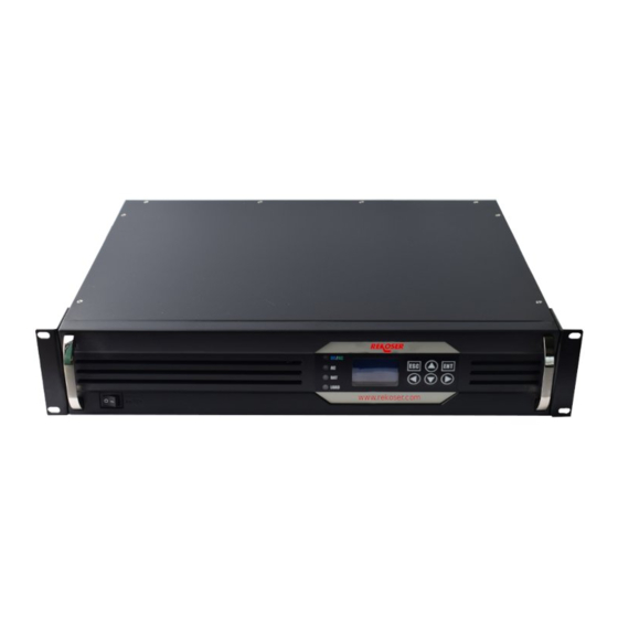
- Page 1 RTI Series Telecom Sine Wave inverter User Manual...
- Page 2 ● Please notice: even if the Mains is cut o , the REKOSER RTI series inverter may still internally have the high voltage able to endanger personal safety.
-
Page 3: Table Of Contents
User Manual for RTI series Table of Contents Chapter I Safety Instruction 1.1 Safety instruction 1.2 General safety protection 1.3 Battery related operation safety protection Chapter II Overview 2.1 Introduction 2.2 Functions and features 2.3 Technical characteristics and parameters 2.3.1 Sine Wave series model code 2.3.2 Sine Wave series model list... - Page 4 User Manual for RTI series 5.2.3 Mute Chapter VI Operation Status and Display 6.1 Indicator light and button definition 6.2 Indicator light display list 6.3 Specification for LCD display menu Chapter VII Alarm and Monitoring 7.1 Remote control and alarm 7.1.1 Interface definition...
-
Page 5: Chapter I Safety Instruction
1.2 General safety protection 1. Do not expose the REKOSER RTI series inverter in the environment including water, fog, snow, dust, etc., and do not block or shield ventilating ducts in order to reduce the danger occurrence probability. Do not install the REKOSER RTI series inverter in a small and narrow unventilated space, or else the power supply will be overheated. -
Page 6: Chapter Ii Overview
Meanwhile, RTI series is not only applicable to the communication industry, but also applicable to other occasions with high requirements for power supply quality, thus becoming the ideal selection of the power supply for o ce automation. -
Page 7: Technical Characteristics And Parameters
LCD panel or communication background software): ● When there are mains, AC-dominated REKOSER RTI series inverter is under mains output mode; in case of mains fault, AC REKOSER RTI series inverter automatically switches to inverter output. -
Page 8: Sine Wave Series Model List
User Manual for RTI series 48-----Nominal input DC voltage (V) 2.3.2 Sine Wave series model list Table I: 24 Series 48 Series 110 Series 230 Series 1000VA 24/ 230-1KVAR 48/ 230-1KVAR 110/ 230-1KVAR 220/ 230-1KVAR 2000VA 24/ 230-2KVAR 48/ 230-2KVAR... - Page 9 User Manual for RTI series By-pass conversion time ≤5ms (ms) Rated capacity (VA) Rated output power (W) 1600 2400 3200 4000 4800 6400 7000 Inverter output voltage 230Vac,50HZ and frequency Inverter output current 3.47 6.96 10.43 13.9 17.4 20.8 27.82 30.43...
- Page 10 User Manual for RTI series Input under-voltage and overvoltage, output overload and short circuit protections, Protection function etc. Table III: 24 Series 48 Series 110 Series 230 Series Rated input 110V 230V voltage (Vdc) Cuto voltage Cuto voltage Cuto voltage...
-
Page 11: Chapter Iii Structure And Principle
Chapter III Structure and Principle 3.1 Hardware structure and working principle Specification: RTI series employs advanced PWM+SPWM high frequency technology and takes CPU as the master control chip, thus realizing the perfect combination of the advanced intelligent control and the mature and stable inverter mode. -
Page 12: Dc Power Supply Mode
User Manual for RTI series 3.2.2 DC power supply mode Namely DC-dominated inverter working mode: under normal condition, DC-dominated inverter is under inverter output status all the time; in case of DC fault, it switches to mains by-pass. 3.3 Appearance and indicator light... -
Page 13: Chapter Iv Installation And Debugging
User Manual for RTI series Chapter IV Installation and Debugging 4.1 Installation preparation RTI series must be installed only by the technical personnel with certain electric theory knowledge and practical experience. 4.1.1 Tool, instrument and data Universal meter, tool kit, specification and cable 4.1.2 Installation environment inspection... -
Page 14: Unpacking And Cargo Inspection
After removing the package, take out the valve bag containing two L-shaped handle frames and handles from the installation accessories, use M4 screw in the bag to fix the right and left sides of the REKOSER RTI series inverter and meanwhile lock the screw, as shown in the following figure:... - Page 15 3. Connecting cable 1) DC input connection Connect the prepared cable to the DC input terminal at the back part of the REKOSER RTI series inverter and pay attention to the connection of the positive and negative electrodes. Hot-line operation shall be forbidden in order to avoid such accidents as short circuit and striking which may endanger personal safety and equipment safety.
-
Page 16: Chapter V Use And Operation
REKOSER RTI series inverter and the mains are normal, the inverter will steadily operate in mains status or inverter status (AC-dominated inverter is steady in mains output status and DC-dominated... -
Page 17: Shutdown
RTI series inverter are both turned o . 5.2.3 Mute In case the REKOSER RTI series inverter has a fault in the operation process, the system will send an audible and visual alarm which can be set through the LCD, namely selecting Turn O (turn-o permanent, and there will be no audible alarm for any new fault) in the sound control option. -
Page 18: Chapter Vi Operation Status And Display
User Manual for RTI series Chapter VI Operation Status and Display 6.1 Indicator light and button definition 6.2 Indicator light display list Mains (Green) Startup Status Mode (Green)→On→ Battery (Green) →On→ Load (Green)→On→ →On→ self-ins pection Buzzer One sound every 1s, and triple sounds before mute. -
Page 19: Specification For Lcd Display Menu
User Manual for RTI series 6.3 Specification for LCD display menu... -
Page 20: Chapter Vii Alarm And Monitoring
User Manual for RTI series Chapter VII Alarm and Monitoring 7.1 Remote control and alarm 7.1.1 Interface definition The contact capacity of each group of the dry contacts shall not exceed 60 V 0.5A. -
Page 21: Common Fault Handling
User Manual for RTI series 7.2 Common fault handling Fault Fault Fault Analysis Fault Point Judgment Fault Handling Remarks Type Phenomenon Check the negative and positive Inverse electrodes of the DC input terminal Confirm the negative connection of DC before connection, wherein the... -
Page 22: Quality Warranty Card
User Manual for RTI series Quality Warranty Card In order to ensure high quality, the sine wave REKOSER RTI series inverter must be strictly inspected before delivery. REKOSER assures the good machine performance and the parts integrity listed in the warranty card to the users. - Page 24 REKOSER C/ Cedro s/n nave 6 Pol. Ind. La Ermita 18230 Atarfe, Granada, Spain +34 958042973 | info@rekoser.com www.rekoser.com...
Need help?
Do you have a question about the RTI Series and is the answer not in the manual?
Questions and answers