Table of Contents

Subscribe to Our Youtube Channel
Summary of Contents for Copper Mountain Technologies ACM4509
- Page 1 631 E New York Street | Indianapolis, IN 46202 USA www.coppermountaintech.com Automatic Calibration Module Revision 21.1 02.11.2021 U.S.: +1.317.222.5400 Singapore: +65.63.23.6546 Latin America: +1.9154.706.5920 EMAE: +44 75 03 69 21 13...
-
Page 2: Table Of Contents
General Overview ..............................7 Modification ........................8 ACM2506 ........................ 10 ACM2509 ........................ 13 ACM2520 ........................ 16 ACM2543 ........................ 19 ACM4509 ........................ 22 ACM4520 ........................ 25 2708 ........................ 29 ACM4000T ......................31 ACM6000T ......................33 ACM8000T ......................36 ACM8400T ......................39 Protective Housing ...................... - Page 3 Contents Connection Diagrams ....................62 Full One-Port Calibration ..................63 One-Path Two-Port and Full Two-Port Calibration ..........64 Full Three-Port Calibration ..................65 Full Four-Port Calibration ..................66 Module Work Session ....................67 Module Preparation for Calibration ..............67 Parameters Setting ..................... 68 Calibration .................................
- Page 4 Contents Cleaning and Care of the Protective Housing ............. 90 Ambient Conditions Control .................. 91 Verification ......................91 Routine Repairs ..............................92 Storage Instructions ............................93 Transportation ..............................94 Annex A — Modules Overview ......................... 95 Annex B — Instruction for Use of the Protective Housing ..........110 Glossary ..................................
-
Page 5: Introduction
Introduction Safety Instructions Carefully read the following safety instructions before putting the Module into operation. Observe all the precautions and warnings provided in this Manual for all the phases of operation, service, and repair of the Module. Observe all general safety precautions related to the operation of electrically energized equipment. - Page 6 · Always wear a grounding wrist strap connected to the desktop anti-static mat via daisy-chained 1MΩ resistor. Definitions of safety symbols used on the instrument and in the manual are listed below. This sign denotes a hazard. It calls attention to a procedure, WARNING practice, or condition that, if not correctly performed or adhered to, could result in injury or death to personnel.
-
Page 7: General Overview
General Overview The Module is designed for calibration (error correction) of Vector Network Analyzers in automatic mode. Calibration is performed by automatically connecting the reflection and transmission impedance states to the VNA test ports. Calibration determines systematic errors in accordance with the VNA model. The process of mathematical compensation (numerical reduction) for measurement systematic errors is called error correction. -
Page 8: Modification
ACM6000T 20 kHz to 6 GHz ACM8000T 100 kHz to 8 GHz 75 Ohm two-port Modules ACM2708 20 kHz to 8 GHz ACM4000T 20 kHz to 4 GHz 50 Ohm four-port Modules ACM4509 100 kHz to 9 GHz Page 8... - Page 9 Module Frequency range ACM4520 100 kHz to 20 GHz ACM8400T 100 kHz to 8 GHz 1 The upper frequency point of ACM2520 and ACM4520 with type N connectors is 18 GHz. 2 The upper frequency point of ACM2543 with 2.92 mm connectors is 40 GHz. Page 9...
-
Page 10: Acm2506
ACM2506 The front panels of the different models of ACM2506 are shown in the figure below. Front panel ACM2506 Page 10... - Page 11 Parts of the ACM2509 Test port The test ports are designed for connection to VNA being calibrated. The VNA connectors, the cross sections of which were calibrated, are referred to as its test ports. The Modules connectors are shown in figures below. Type N, male Type N, female 3.5 mm, male...
- Page 12 Hardware configurations Model Connector type Port A Port B ACM2506-011 type N, female type N, female ACM2506-012 type N, male type N, female ACM2506-111 3.5 mm, female 3.5 mm, female ACM2506-112 3.5 mm, male 3.5 mm, female Page 12...
-
Page 13: Acm2509
ACM2509 Front panel of different models of ACM2506 are shown in figure below. Front panel ACM2509 Page 13... - Page 14 Parts of Module Test port The test ports are designed for connection to VNA being calibrated. The VNA connectors, the cross sections of which were calibrated, are referred to as its test ports. The Modules connectors are shown in figures below. Type N, male Type N, female 3.5 mm, female...
- Page 15 Hardware configurations Model Connector type Port A Port B ACM2509-011 type N, female type N, female ACM2509-012 type N, male type N, female ACM2509-111 3.5 mm, female 3.5 mm, female ACM2509-112 3.5 mm, male 3.5 mm, female Page 15...
-
Page 16: Acm2520
ACM2520 The front panels of the different models of ACM2520 are shown in the figure below. Front panel ACM2520 Page 16... - Page 17 Parts of Module Test port The test ports are designed for connection to VNA being calibrated. The VNA connectors, the cross sections of which were calibrated, are referred to as its test ports. The Modules connectors are shown in figures below. Type N, male Type N, female 3.5 mm, female...
- Page 18 · Red LED indicator means warm-up mode of the Module. The time required for operating mode setting is automatically counted from the moment of the Module connection using USB. If the Module is disconnected during setting and reconnected again, then the countdown counter starts from the beginning. Additional red LED may indicate the Module connection loss with the PC.
-
Page 19: Acm2543
ACM2543 The rear panels of the different models of ACM2543 are shown in the figure below. Rear panel ACM2543 Page 19... - Page 20 Parts of Module Test port The test ports are designed for connection to VNA being calibrated. The VNA connectors, the cross sections of which were calibrated, are referred to as its test ports. The Modules connectors are shown in figures below. 2.4 mm (2.92 mm), female 2.4 mm (2.92 mm), male LED Status Indicator...
- Page 21 Hardware configurations Model Connector type Port A Port B ACM2543-611 2.92 mm, female 2.92 mm, female ACM2543-612 2.92 mm, male 2.92 mm, female ACM2543-711 2.4 mm, female 2.4 mm, female ACM2543-712 2.4 mm, male 2.4 mm, female Page 21...
-
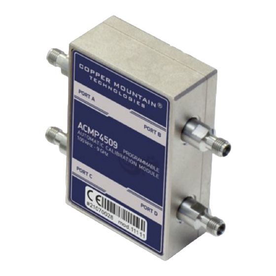
Page 22: Acm4509
ACM4509 The front panels of the different models of ACM4509 are shown in the figure below. Page 22... - Page 23 Front panel ACM4509 Parts of Module Test port The test ports are designed for connection to VNA being calibrated. The VNA connectors, the cross sections of which were calibrated, are referred to as its test ports. The Modules connectors are shown in figures below.
- Page 24 Module and repeat the connection. · Green LED indicator means the Module is ready for operation. Hardware configurations Model Connector type Port A/C Port B/D ACM4509-01111 type N, female type N, female ACM4509-01212 type N, male type N, female ACM509-11111 3.5 mm, female 3.5 mm, female...
-
Page 25: Acm4520
ACM4520 The front panels of the different models of ACM4520 are shown in the figure below. Page 25... - Page 26 Front panel ACM4520 Parts of Module Test port The test ports are designed for connection to VNA being calibrated. The VNA connectors, the cross sections of which were calibrated, are referred to as its test ports. The Modules connectors are shown in figures below. Page 26...
- Page 27 Type N, male Type N, female 3.5 mm, female 3.5 mm, male Connector (on side panel) The connector is located on the bottom of the Module and is intended for the Module connection to the controlling PC. The Module is powered using the USB cable. LED Status Indicator (on rear panel) NOTE LED Status Indicator is located under the label and is visible...
- Page 28 Hardware configurations Model Connector type Port A/C Port B/D ACM4520-01111 type N, female type N, female ACM4520-01212 type N, male type N, female ACM4520-11111 3.5 mm, female 3.5 mm, female ACM4520-11212 3.5 mm, male 3.5 mm, female Page 28...
- Page 29 2708 The front panels of the different models of ACM2708 are shown in the figure below. Front panel ACM2708 Parts of Module Test port The test ports are designed for connection to VNA being calibrated. The VNA connectors, the cross sections of which were calibrated, are referred to as its test ports.
- Page 30 Connector (on side panel) The connector is located on the bottom of the Module and is intended for the Module connection to the controlling PC. The Module is powered using the USB cable. Hardware configurations Model Connector type Port A Port B ACM2708-511 type N 75, female...
-
Page 31: Acm4000T
ACM4000T The front panels of the different models of ACM4000T are shown in the figure below. Front panel ACM4000T Parts of Module Test port The test ports are designed for connection to VNA being calibrated. The VNA connectors, the cross sections of which were calibrated, are referred to as its test ports. - Page 32 Connector (on side panel) The connector is located on the bottom of the Module and is intended for the Module connection to the controlling PC. The Module is powered using the USB cable. Hardware configurations Model Connector type Port A Port B ACM4000T-511 type N 75, female...
-
Page 33: Acm6000T
ACM6000T The front panels of the different models of ACM6000T are shown in the figure below. Front panel ACM6000T Page 33... - Page 34 Parts of Module Test port The test ports are designed for connection to VNA being calibrated. The VNA connectors, the cross sections of which were calibrated, are referred to as its test ports. The Modules connectors are shown in figures below. Type N, male Type N, female 3.5 mm, female...
- Page 35 Hardware configurations Model Connector type Port A Port B ACM6000T-011 type N, female type N, female ACM6000T-012 type N, male type N, female ACM6000T-111 3.5 mm, female 3.5 mm, female ACM6000T-112 3.5 mm, male 3.5 mm, female Page 35...
-
Page 36: Acm8000T
ACM8000T The front panels of the different models of ACM8000T are shown in the figure below. Front panel ACM8000T Page 36... - Page 37 Parts of Module Test port The test ports are designed for connection to VNA being calibrated. The VNA connectors, the cross sections of which were calibrated, are referred to as its test ports. The Modules connectors are shown in figures below. Type N, male Type N, female 3.5 mm, female...
- Page 38 Hardware configurations Model Connector type Port A Port B ACM8000T-011 type N, female type N, female ACM8000T-012 type N, male type N, female ACM8000T-111 3.5 mm, female 3.5 mm, female ACM8000T-112 3.5 mm, male 3.5 mm, female Page 38...
-
Page 39: Acm8400T
ACM8400T The front panels of the different models of ACM8400T are shown in the figure below. Page 39... - Page 40 Front panel ACM8400T Parts of Module Test port The test ports are designed for connection to VNA being calibrated. The VNA connectors, the cross sections of which were calibrated, are referred to as its test ports. The Modules connectors are shown in figures below. Type N, male Type N, female 3.5 mm, female...
- Page 41 Connector (on side panel) The connector is located on the bottom of the Module and is intended for the Module connection to the controlling PC. The Module is powered using the USB cable. LED Status Indicator (on rear panel) NOTE LED Status Indicator is located under the label and is visible only during operation.
-
Page 42: Protective Housing
Protective Housing The protective housing is designed to protect the test ports and the USB connector of the automatic calibration module (ACM) from mechanical influences. The protective housing is removable. The collapsible design allows for quick installation. The protective housing is non-repairable. NOTE The protective housing is not intended for use in extreme environments. - Page 43 Compatible ACM models Housing Model ACM2520-011, ACM2520-012, ACM2520 ACM2520-111, ACM2520-112 ACM2543 ACM2543-611, ACM2543-612, ACM2543-711, ACM2543-712 ACM4509-01111, ACM4509-01212, ACM4509 ACM4509-11111, ACM4509-11212, ACM84000T-01111, ACM84000T- 01212, ACM84000T-11111, ACM84000T- 11212 Page 43...
- Page 44 Compatible ACM models Housing Model ACM4520-01111, ACM4520-01212, ACM4520 ACM4520-11111, ACM4520-11212 Page 44...
-
Page 45: Delivery Kit
Delivery Kit The delivery kit for the Module is represented in table below. Name Quantity, pcs Automatic calibration module USB cable Envelope with ACM certificate of calibration and statement of calibration due date Protective housing 1. A specific model of Module is selected in the order. 2. -
Page 46: Specifications
Specifications The specifications of each Module can be found in its datasheet. Page 46... -
Page 47: Measurement Capabilities
Measurement Capabilities The VNA software controlling the Module features a wide range of functions. They are briefly described below. See the VNA operating manual for more detailed information. Automatic Calibration Calibration Calibration of a test setup (which includes VNA, cables, adapters) significantly increases the accuracy of measurements. - Page 48 One-path two-port calibration The method of calibration performed for reflection one-way transmission measurements. example, measuring S11 and S21 only. It ensures high accuracy reflection measurements, and reasonable accuracy for transmission measurements. Full two-port calibration The method of calibration performed for full S parameter matrix measurement of a two-port DUT.
- Page 49 Characterization Characterization Characterization table parameters of all the states of the Module switches, stored in its memory. The Module has two memory sections. The first one is write-protected and contains factory characterization. The second memory section allows to store up to three user characterizations.
- Page 50 Automatic Orientation Orientation Orientation refers to the Module ports in relation to the test ports of the VNA. While the VNA ports are indicated by numbers, the Module ports are indicated by the letters A, B, C and D. Orientation method Manual or automatic orientation method can be selected.
- Page 51 Confidence Check Confidence check The confidence check is a test of the current calibration, performed either by the Module, or by any other method. confidence check features simultaneous indication of attenuator S- parameters measured and stored in the Module memory. Math (division) function for data and memory used...
-
Page 52: Principle Of Operation
ACM2543, 10 reflection states (five for each port), a THRU, and an ACM8000T attenuator. ACM4509, 16 reflection states (four for each port), a THRU, and an ACM8400T attenuator. ACM4520 12 reflection states (three for each port), a THRU, and an attenuator. -
Page 53: Types Of Calibration Standards
Types of Calibration Standards Calibration standards are physical devices with known parameters used for VNA calibration, with the purpose of calculating systematic errors and further correcting the measurement results. OPEN, SHORT, and LOAD are the reflection standards, and THRU is the transmission standard (transmission connection). -
Page 54: Module Block Diagrams
Module Block Diagrams Module block diagrams are shown in table below. Block diagram of ACM2506 and ACM2509 Block diagram of ACM2520... - Page 55 Block diagram of ACM4509 and ACM8400T...
- Page 56 Block diagram of ACM4520...
- Page 57 Block diagram of ACM2708, ACM4000T and ACM6000T Block diagram of ACM8000T and ACM2543...
-
Page 58: Preparation For Use
Preparation for Use Unpack the Module and other accessories. Please keep packaging to safely ship the instrument for CAUTION annual calibration! The following section describes the process of preparing the ACM for use: · Operating Restrictions. · Installation. · Software. Operating Restrictions The accuracy of calibration using the Module largely depends on proper handling of the Module while preparing it for use. - Page 59 The main cause of measurement accuracy deterioration is the change of ambient conditions between the calibration and DUT measurement. The ambient conditions are described in Ambient Conditions Control. Page 59...
-
Page 60: Installation
Installation Unpack the Module and place the Module in the work area. Take necessary precautions to protect against electrostatic discharge in the work area. Keep the Module in operating conditions for no less than two hours if it was stored in any other ambient conditions. -
Page 61: Software
Software The Module is controlled by the Copper Mountain Technologies VNA software. Minimum technical requirements to the PC and the description of software installation are described in the VNA Operating Manual. The VNA software automatically detects the connected Module and makes the Autocalibration menu available. -
Page 62: Operation Procedure
Operation Procedure This section describes how to work with the Module: · Connection diagrams to perform calibration. · Module work session. · Parameters setting. Connection Diagrams The following are connection diagrams for calibrations: · Full One-Port Calibration · One-Path Two-Port and Full Two-Port Calibration ·... -
Page 63: Full One-Port Calibration
Full One-Port Calibration In order to perform calibration, it is recommended to connect a LOAD to a free port of the Module. The LOAD is not included in the delivery kit. Typical connection diagram for full one-port calibration is shown in figure below. Module connection diagram for performing full one-port calibration To prevent the cable from damage and improve the stability, it is recommended to use additional protection metrology-grade adapters (these adapters are not shown in... -
Page 64: One-Path Two-Port And Full Two-Port Calibration
One-Path Two-Port and Full Two-Port Calibration Typical connection diagram for one-path two-port and full two-port calibration is shown in figure below. Module connection diagram for performing one-path two-port and full two-port calibration Page 64... -
Page 65: Full Three-Port Calibration
Full Three-Port Calibration In order to perform calibration, connect a LOAD to a free port of the Module. A typical connection diagram for performing full three-port calibration is shown in the figure below. Module connection diagram for performing full three-port calibration using ports 1, 2 and 4 Page 65... -
Page 66: Full Four-Port Calibration
Full Four-Port Calibration A typical connection diagram for performing full four-port calibration is shown in the figure below. Module connection diagram for performing full four-port calibration Page 66... -
Page 67: Module Work Session
Module Work Session This section includes the example of the Module work session. Perform the following activities to calibrate all types of VNAs: · Locate the Module at the work site and warm it up for at least 15 minutes. ·... -
Page 68: Parameters Setting
Parameters Setting Before starting measurements and calibration, set up the following VNA parameters: · Set up default parameters. · Select the traces and assign measured S-parameters to them. · Set up the frequency range and the number of frequency points. ·... -
Page 69: Calibration
Calibration The following section describes the process of calibrating ACMs. Module Advantages Calibration involving the Module has several advantages compared to conventional calibration with a kit of mechanical calibration standards: · Only one connection required. · Reduced calibration time. · Less probability of operator’s mistakes. -
Page 70: Measurement Errors
Measurement Errors Different measurement errors affect the results of VNA S-parameter measurements. The measurement errors can be divided into two categories: · Systematic errors. · Random errors. Random errors are: · Noise fluctuations and thermal drift in electronic components. · Changes in the mechanical dimensions of cables and connectors subject to temperature drift. -
Page 71: Calibration Types
Calibration Types The Modules enable three types of calibration: · Full one-port calibration · One-path two-port calibration · Full two-port calibration Four-port Modules additionally enable two types of calibration: · Full three-port calibration · Full four-port calibration The calibration procedure is described in Calibration Procedure. -
Page 72: Full Two-Port Calibration
Full Two-Port Calibration Full two-port calibration requires connection of seven calibration standards: · Two OPEN calibration standards. · Two SHORT calibration standards. · Two LOAD calibration standards. · One two-port THRU calibration standard. This calibration type combines two one-port calibrations for each test port with the measurement of transmission and reflection of a THRU standard in both directions. -
Page 73: Unknown Thru
Unknown Thru Unknown thru is used in full two-, three-, and four-port calibration. The calibration type with an unknown thru is called SOLR, which refers to Short, Open, Load, Reciprocal. Any arbitrary reciprocal two-port device with unknown parameters can be used as an unknown thru. -
Page 74: Thermal Compensation
Thermal Compensation Thermal compensation is a software function of the Module parameters correction using the data of internal temperature sensor and data on temperature dependence. The Module temperature dependence data are the thermal compensation coefficients of magnitude and phase of reflection or transmission coefficients for different Module states stored in its memory. -
Page 75: Calibration Procedure
Calibration Procedure Calibration is performed in fully automatic mode. The calibration procedure is the following: 1. Press the calibration softkey in the software main menu. 2. Select automatic calibration in the resulting menu. The autocalibration softkey becomes active after the Module connection (typical connection diagrams are shown in Connection Diagrams). - Page 76 Autocalibration algorithm The calibration will be performed automatically: the standards from the Module set will be connected to VNA in sequence under the VNA software control. Then the calibration coefficients table will be calculated and stored in the VNA memory. When calibration is completed, certain icons will be indicated in the status bars of reflection and transmission coefficients traces: ·...
- Page 77 · [F2] — full two-port calibration. · [F3] — full three-port calibration. · [F4] — full four-port calibration. Detailed information on calibration using the Module and the names of all softkeys for all VNAs can be found in the VNA Operating and Programming Manual. Page 77...
-
Page 78: User Characterization Procedure
User Characterization Procedure Characterization is the process of calculation of S-parameters table for all Module states. User characterization of the Module is required if the Module connectors were modified using the adapters. The new device, including the Module and adapters, is characterized. - Page 79 User characterization algorithm Detailed information on the Module user characterization and the names of all softkeys for all VNAs can be found in the VNA Operating and Programming Manual. Page 79...
-
Page 80: Confidence Check
Confidence Check Confidence check is a test of current calibration performed either using the Module or any other method. The Module features an additional attenuator state that is not used during calibration. The attenuator is intended for checking calibration by means of a special software function, which enables comparison of measured attenuator S-parameters and the values stored in the Module memory. - Page 81 Algorithm of confidence check using the Module Detailed information on the Module confidence check and the names of all softkeys for all VNAs can be found in the VNA Operating and Programming Manual. Page 81...
-
Page 82: Automation
Automation The Module supports remote control using third party software. The control function is implemented by means of USB protocol. The VISA library must be installed on the PC for interaction. The library allows for controlling of measuring equipment in almost any programming language, i.e. -
Page 83: Maintenance
Maintenance This section establishes the procedure and rules of maintenance, enabling constant Module operational readiness. The purpose of Module maintenance is to control its performance parameters and secure its service life. Maintenance Procedure The Maintenance Procedure is as follows: · Maintenance Activities ·... -
Page 84: Maintenance Activities
Maintenance Activities The Module maintenance includes the following activities: · Inspection. · Functional test. The inspection should be done every time before and after the Module is used. The inspection comprises: · Checking components against the delivery kit list. · Cleaning dust and dirt from external surfaces of the Module. -
Page 85: Cleaning Connectors
Cleaning Connectors Clean the connectors before and after connecting the Module. The procedure of cleaning connectors: 1. Wipe the connector surfaces as shown by the arrows in the figures below with a swab dipped in alcohol. Type N connectors 2.4 mm, 2.92 mm, 3.5 mm connectors 2. -
Page 86: Gauging Connectors
Gauging Connectors Gauge the connectors before using the Module for the first time, and regularly during operation. The first gauging of connectors obtains pin depth, which can be used during the Module operation to evaluate its changing. Gauge the connectors again if: ·... - Page 87 pin depth value of Module ports connectors must be within the following ranges: Connectors type Pin depth range Type N, female 5.18 to 5.26 mm Type N, male 5.28 to 5.36 mm 2.4 mm, 2.92 mm, 3.5 mm, male - 0.08 to 0.00 mm 2.4 mm, 2.92 mm, 3.5 mm, female - 0.08 to 0.00 mm The A pin depth value ranges for connectors of other devices are be indicated in their...
-
Page 88: Connecting And Disconnecting Devices
Connecting and Disconnecting Devices The Module connectors should be connected in the following order: 1. Fix the housing of one of the devices being connected. This is necessary to avoid its displacement during connection. Fix the device by any of the following ways: ·... - Page 89 2.4 mm, 2.92 mm, 3.5 mm connectors (female on the left, male on the right) Disconnect the connectors in the following order: 1. Using the torque wrench, which was used for tightening, loosen the male connector nut, while holding the device by hand or an open-end wrench to prevent it from turning.
-
Page 90: Cleaning And Care Of The Protective Housing
Cleaning and Care of the Protective Housing The protective housing is not intended for use in extreme environments. Do not bend or stretch the protective housing during use. Clean the protective housing with a lint-free cloth, slightly dampened with water. Clean the protective housing when it is disassembled. -
Page 91: Ambient Conditions Control
The measurements should be performed at an ambient temperature within ±1 °C of the temperature at the time VNA calibration. Verification Copper Mountain Technologies recommends following the industry’s best practices and user quality policies to determine the ACM verification period. Consider frequency of use, environmental conditions, and storage procedures. The suggested verification interval is 1-3 years. -
Page 92: Routine Repairs
Routine Repairs Only authorized routine repair or repair by the licensed company is permitted. The repair method is non-differential. Routine repairs Repairs performed to enable or restore the device performance, which includes replacement and/or recovery of separate parts. Non-differential The method of repairs at which the restored constituent parts method do not belong to the specific device instance. -
Page 93: Storage Instructions
Storage Instructions Module can be stored in the factory packaging at 0 to +40 ºC and a relative humidity of up to 80% (at 25 ºC). After the factory packaging is removed, the Module should be stored at +10 to +35 ºC and relative humidity up to 80% (at 25 ºC). Keep the storage facilities free from dust, fumes of acids and alkalis, aggressive gases, and other chemicals, which can cause corrosion. -
Page 94: Transportation
Transportation Load and unload the Module packages carefully, avoiding shock and packaging damage. Use the markings on the package to place the Modules correctly during transportation. The Modules must be shipped in any closed vehicle at temperature from -50 to +70 ºC, a relative humidity of 95% (at 30 ºC), and an atmospheric pressure of 70 to 106.7 kPa (537 to 800 mm Hg). -
Page 95: Annex A - Modules Overview
Annex A — Modules Overview Module Frequency range Supported Features calibrations Characterization points Number of ports Port connector ACM2506 - 011 20 kHz to 6.5 GHz Full one-port Unknown thru 2 to 1601 One-path two-port Thermal compensation 2 ports Full two-port User characterization type N (50 Ohm) Automatic orientation... - Page 96 Module Frequency range Supported Features calibrations Characterization points Number of ports Port connector ACM2506 - 112 20 kHz to 6.5 GHz Full one-port Unknown thru 2 to 1601 One-path two-port Thermal compensation 2 ports Full two-port User characterization 3.5 mm (50 Ohm) Automatic orientation Confidence check ACM2509 - 011...
- Page 97 Module Frequency range Supported Features calibrations Characterization points Number of ports Port connector ACM2509 - 111 20 kHz to 9 GHz Full one-port Unknown thru 2 to 1601 One-path two-port Thermal compensation 2 ports Full two-port User characterization 3.5 mm (50 Ohm) Automatic orientation Confidence check ACM2509 - 112...
- Page 98 Module Frequency range Supported Features calibrations Characterization points Number of ports Port connector ACM2520 - 012 100 kHz to 18 GHz Full one-port Unknown thru 2 to 1601 One-path two-port Thermal compensation 2 ports Full two-port User characterization type N (50 Ohm) Automatic orientation Confidence check ACM2520 - 111...
- Page 99 Module Frequency range Supported Features calibrations Characterization points Number of ports Port connector ACM2543 - 611 10 MHz to 40 GHz Full one-port Unknown thru 2 to 1601 One-path two-port Thermal compensation 2 ports Full two-port User characterization 2.92 mm (50 Ohm) Automatic orientation Confidence check ACM2543 - 612...
- Page 100 One-path two-port Thermal compensation 2 ports Full two-port User characterization 2.4 mm (50 Ohm) Automatic orientation Confidence check ACM4509 - 01111 100 kHz to 9 GHz Full one-port Unknown thru 2 to 1601 One-path two-port Thermal compensation 4 ports Full two-port...
- Page 101 Module Frequency range Supported Features calibrations Characterization points Number of ports Port connector ACM4509 - 11111 100 kHz to 9 GHz Full one-port Unknown thru 2 to 1601 One-path two-port Thermal compensation 4 ports Full two-port User characterization 3.5 mm (50 Ohm)
- Page 102 Module Frequency range Supported Features calibrations Characterization points Number of ports Port connector ACM4520 - 01111 100 kHz to 20 GHz Full one-port Unknown thru 2 to 1601 One-path two-port Thermal compensation 4 ports Full two-port User characterization type N (50 Ohm) Full three-port Automatic orientation Full four-port...
- Page 103 Module Frequency range Supported Features calibrations Characterization points Number of ports Port connector ACM4520 - 11111 100 kHz to 20 GHz Full one-port Unknown thru 2 to 1601 One-path two-port Thermal compensation 4 ports Full two-port User characterization 3.5 mm (50 Ohm) Full three-port Automatic orientation Full four-port...
- Page 104 Module Frequency range Supported Features calibrations Characterization points Number of ports Port connector ACM2708 - 511 20 kHz to 4 GHz Full one-port Unknown thru 2 to 1601 One-path two-port Thermal compensation 2 ports Full two-port User characterization type N (75 Ohm) Automatic orientation Confidence check ACM2708 - 512...
- Page 105 Module Frequency range Supported Features calibrations Characterization points Number of ports Port connector ACM4000T - 512 20 kHz to 4 GHz Full one-port Unknown thru 2 to 1601 One-path two-port Thermal compensation 2 ports Full two-port User characterization type N (75 Ohm) Automatic orientation Confidence check ACM6000T - 011...
- Page 106 Module Frequency range Supported Features calibrations Characterization points Number of ports Port connector ACM6000T - 111 20 kHz to 6 GHz Full one-port Unknown thru 2 to 1601 One-path two-port Thermal compensation 2 ports Full two-port User characterization 3.5 mm (50 Ohm) Automatic orientation Confidence check ACM6000T - 112...
- Page 107 Module Frequency range Supported Features calibrations Characterization points Number of ports Port connector ACM8000T - 012 100 kHz to 8 GHz Full one-port Unknown thru 2 to 1601 One-path two-port Thermal compensation 2 ports Full two-port User characterization type N (50 Ohm) Automatic orientation Confidence check ACM8000T - 111...
- Page 108 Module Frequency range Supported Features calibrations Characterization points Number of ports Port connector ACM8400T - 01111 100 kHz to 8 GHz Full one-port Unknown thru 2 to 1601 One-path two-port Thermal compensation 4 ports Full two-port User characterization type N (50 Ohm) Full three-port Automatic orientation Full four-port...
- Page 109 Module Frequency range Supported Features calibrations Characterization points Number of ports Port connector ACM8400T - 11111 100 kHz to 8 GHz Full one-port Unknown thru 2 to 1601 One-path two-port Thermal compensation 4 ports Full two-port User characterization 3.5 mm (50 Ohm) Full three-port Automatic orientation Full four-port...
-
Page 110: Annex B - Instruction For Use Of The Protective Housing
Annex B — Instruction for Use of the Protective Housing Procedure for installing (removing) the protective housing: 1. Unscrew using a PH1(PZ1) screwdriver: · 4 pcs. M3×22 screws on the ACM cover. Remove the ACM cover (See figure below). · 2 pcs. - Page 111 Example of housing installation (for ACM2509-011) Page 111...
-
Page 112: Glossary
Glossary Prefixes µ micro (10 milli (10 kilo (10 Mega (10 Giga (10 Number / Symbols Ω decibel decibels above 1 milliwatt Watt Farad Henry Hertz meter second Volt Page 112... - Page 113 The following abbreviations are used in this manual: Automatic Calibration Module Copper Mountain Technologies Direct current Device Under Test Light-emitting diode Personal Computer Vector Network Analyzer Universal Serial Bus Page 113...
-
Page 114: Copyright
Copper Mountain Technologies. Copper Mountain Technologies respects the intellectual property of others, and we ask our users to do the same. CMT software is protected by copyright and other intellectual property laws.
Need help?
Do you have a question about the ACM4509 and is the answer not in the manual?
Questions and answers