Table of Contents
Advertisement
Quick Links
Advertisement
Table of Contents

Subscribe to Our Youtube Channel
Summary of Contents for iGuard IP-220E
- Page 1 Guard IP-220E IP/Network Camera User’s Manual Version 2.5...
-
Page 2: Table Of Contents
Chapter 1 Introduction _________________________________________ 3 1.1 Features ________________________________________________ 3 1.2 Function ________________________________________________ 3 1.3 Package Contents_________________________________________ 4 Chapter 2 iGuard IP-220E Hardware______________________________ 5 Chapter 3 Hardware Installation _________________________________ 6 3.1 Installation Procedure ______________________________________ 7 Chapter 4: iGuardware_________________________________________ 8 4.1 Installing iGuardware ______________________________________ 8 4.2 Using iGuardware _________________________________________ 9... - Page 3 5.2.3.2 Network_____________________________________________ 41 5.2.3.3 Account Settings ______________________________________ 44 5.2.4 Advanced Settings ______________________________________ 46 5.2.4.1 Event Notification _____________________________________ 46 5.2.4.2 Motion Detection______________________________________ 50 5.2.4.3 Image Recording _____________________________________ 53 5.2.4.4 E-mail / FTP _________________________________________ 54 5.2.4.5 System Settings ______________________________________ 57 5. 2.4.7 About ______________________________________________ 59 Appendix A: Router Configuration ______________________________ 61 Appendix B: IP Address, Subnet and Gateway ____________________ 79 Appendix C: Glossary ________________________________________ 81...
-
Page 4: Chapter 1 Introduction
IP, account and password. Each system can simultaneously support any one combinations of USB PC cameras be it regular, infrared or pan-tilt. With its built-in web-server, iGuard-IP-220E can stream video images directly to the Internet without have to go through a computer.iGuard-IP-220E features a Windows-based software that allows the user to... -
Page 5: Package Contents
China, and if he or she likes, also check on the branch office in Singapore at the same time. 1.3 Package Contents Your iGuard package should contain the following items; 1. iGuard IP-220E Network Camera, 2. Ethernet Cable 3. iGuard Utility CD/Software 4. Quick Installation Guide 5. -
Page 6: Chapter 2 Iguard Ip-220E Hardware
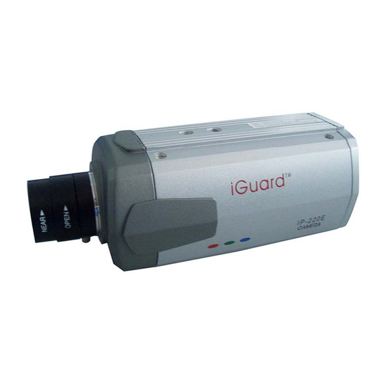
Chapter 2 iGuard IP-220E Hardware Fig.2 iGuard IP-220E Camera LED Status Indicators on iGuard Light color Signal definition Green Power state Error Condition Orange Logon state Yellow USB data activity Table.1 iGuard Status LED Indicator Light indicators on iGuard LAN Port LED... -
Page 7: Chapter 3 Hardware Installation
Before you start using the iGuard IP-220E network camera, you will need to set-up both the hardware and software. The following is a flow chart on the installation procedure: Connect network cable, and power Connect Network cable to ROUTER (Chapter 4) and iGuard-Viewer Router Programming (Appendix). -
Page 8: Installation Procedure
IP-220E. Step 3: Connect DC power adapter output into iGuard IP-220E socket. Warning: Please make sure the input Voltage and Frequency of the DC power adapter (DC 5.3V) is correct before plugging into the power outlet! -
Page 9: Chapter 4: Iguardware
iGuardware is a collection of two utility programs: iGuard Utility and iGuardview. You can use the iGuard Utility to quickly setup multiple iGuard units and you can use iGuardview to monitor multiple cameras, and maybe most importantly to perform motion tracking (V2.5 and above only). If you have a DHCP server on the network, the iGuard will obtain an IP address automatically, and you can enter this IP address in IE to launch the web manager (Chapter 5). -
Page 10: Using Iguardware
If the password on your unit is disabled by your dealer and you are on the same LAN (same subnet) then you can use the web manager to configure the iGuard IP-220E camera by simply double click on the serial # of the camera. Everything discussed in this chapter can be repeated in Chap.5... -
Page 11: Setup Wizard
4.2.1.1 Setup Wizard “Setup Wizard” will take you through the basic configurations step by step. 1. Click to highlight the iGuard on the right that you want to configure. 2. Click on “Setup Wizard”. First, you must enter the device password located on the serial label to enter “Setup Wizard”;... - Page 12 4. Enter the necessary camera configurations. Choose the appropriate frequency (Indoor 60 Hz, Indoor 50 Hz or Outdoor) to prevent flickering on the video feed. Enter a name for the camera in the “Location” box to easily identify it. 5. Click “Next >” to configure the Network Connection. “Obtain an IP address by DHCP”...
- Page 13 Chapter 4: iGuardware Fig.7 iGuard a/DSL Setup Select “Enable PPPoE connection” and enter your account and password details as provided by your internet service provider (“ISP”). Otherwise, leave it at the default “Disable PPPoE connection” 7. Click “Next >” to change your administrator account and password information. Fig.8 iGuard a/DSL Account Setup An administrator account is necessary to ensure privacy.
-
Page 14: Launch Iguard
password. To reset the iGuard account password, you will need to re-install the firmware using iGuard Utility. 8. Click “Next >” to upload these configuration to iGuard. 9. Click “Next >” to save and restart iGuard with the new configurations. 4.2.1.2 Launch iGuard Once you have finished with the above Setup Wizard, either click “Launch iGuard”... - Page 15 Manager(Chapter.5). Key in the account name and password entered earlier (if you did not configure one, then revert to the default name “admin” and device password, OR just press ENTER or click on the “Apply” button, if the account name and password was not set and have been deleted).
-
Page 16: Ip Configuration
4.2.1.3 IP Configuration This section allows you to set the IP configuration for iGuard. Select the iGuard on the right display screen, and then click “IP Configuration”. This will bring up the IP Address Configuration window. There are two tabs; •... - Page 17 Chapter 4: iGuardware Fig.12 IP Configuration: Set an IP Address for iGuard Once the IP Address is set, you will be able to connect to iGuard webpage by entering this IP Address into a standard browser. “Obtain an IP address by DHCP or BOOTP” The IP address, Subnet Mask and Gateway is acquired directly and assigned automatically by the system.
- Page 18 Device Password Use this to set an access password to the individual device. Once set, the user must enter the password to access the device. In addition, the IP Address will not be shown on the right display panel of iGuard Utility. Note: The default device password is set to be the same as administrator password, which is the printed on the serial label.
-
Page 19: Upgrade Firmware
Management Protocol The administrator can determine the parameter settings when providing access via HTTP (web) to iGuard. For security reasons, the administrator can choose to use either an open or advanced port setting to control these access. The default values are set to port number 80 for HTTP. Once the HTTP port number is set to another port (other than 80), the full IP Address must be entered in order to access the Website. - Page 20 Chapter 4: iGuardware 3. Select new firmware file (*.bin) and, 4. Click “Start”. The iGuard red and yellow LED will flash alternately to indicate that firmware upgrading is in progress. Once completed, iGuard will reboot. NOTE: If the downloading / upgrade process is interrupted or the data is corrupted, the iGuard may become non-functional which is not covered by the standard warranty...
-
Page 21: Iguardview
Chapter 4: iGuardware 4.2.2 iGuardView iGuardView is a PC based utility software that allow you to manage and monitor multiple iGuard cameras located either in a LAN or on a WAN, You can launch the iGuardView program by clicking on “start” - “Program” - “iGuard” - “iGuardView”... -
Page 22: Device Setting
4.2.2.1 Device Setting Press the “Enumerate” button, iGuardView will start a search for all iGuard cameras under the same subnet and list them in the main window. Once detected, the following will show in the main window: This shows that the camera is online and active. This shows that the camera is off-line Manually adds the iGuard to be monitored. - Page 23 Highlight the iGuard to be deleted from iGuardView’s list. Click “Yes” to confirm deletion of selected iGuard. Use this function to change iGuard Address & Port Number. Chapter 4: iGuardware...
-
Page 24: Camera Setting
4.2.2.2 Camera Setting Camera Select: Account: Password: Image Zoom: Camera Rotation: Mirror the Image: Maximum frame per second: Time and Date Chapter 4: iGuardware Select either camera A or B If you have setup user account, the information must be entered here. Otherwise access will be denied. -
Page 25: Motion Detection Setting
4.2.2.3 Motion Detection Setting Enable Motion Detect Sensitivity Window on-top when Motion Detected Mark Motion Detected object in Track Moving Object Image Recording Chapter 4: iGuardware Click checkbox to Detection. Note: This feature requires the Camera Window be active to work. Click “Monitor” to activate the Window. - Page 26 Image Choose Compression: compressions. Note: This list is dependent on the Codec that is available or already installed on the local PC. To record in MPEC-4, make sure you install or upgrade to Windows Media Player v10. Recording AVI File Location where the file will be recorded to.
-
Page 27: Email Notification Setting
Chapter 4: iGuardware 4.2.2.4 Email Notification Setting You will need to configure the “Message Sender Information” in order for iGuard to send emails. Server Authentication Click “settings…” Enter your Account Name and Account Password if your Server Requires Authentication. Email Address Click “Add…”... -
Page 28: Snmp Setting
Click “Modify…” to modify the entered Email Address Click “Delete” to remove an email address from the notification list. 4.2.2.5 SNMP Setting Host Name: Provide a Name to identify this device. HTTP Port: Enter the HTTP port assigned for iCAMView. Location: Provide a location for SNMP manager to track device. -
Page 29: Camera Monitor
Chapter 4: iGuardware 4.2.2.6 Camera Monitor : Highlight the iCAMView in the main windows display, and click “Monitor” to view the video stream. Move the curser over the edges of the picture and it will turn into an arrow. Click and hold to pan / tilt the camera (if the camera supports this function) Click this button to record the current image on screen. - Page 30 Chapter 4: iGuardware Click this to switch to full screen view. Double click to switch back to current view. Click and drag to resize the window and it’s contents. Date and Time display of live streaming video. Click the left side of the viewing window to bring out more control features.
- Page 31 Click the depressed window size. b. Custom update Window -- use this if you want to monitor only a specific area within the viewing window. On the video window, RIGHT click, hold and drag to the desired window zoom size. A thin line will outline the chosen window size.
-
Page 32: View
Click once to tilt the camera up by 1 deg. Click and hold and the camera will tilt increasingly faster upwards. Click once to tilt the camera down by 1 deg. Click and hold and the camera will tilt increasingly faster downwards. -
Page 33: Help
Set the SNMP Parameter. 4.2.2.9 Help Help Display iGuardView version, Copyright information and product service contact. Chapter 4: iGuardware... -
Page 34: Chapter 5: Iguard Web Manager
Chapter 5: iGuard Web Manager Chapter 5: iGuard Web Manager 5.1 Introduction If you have connected the iGuard to an internal network with a DHCP server, the IP property (IP address, Mask, and Gateway) will be automatically assigned. 1. Start the Web Brower (Netscape or Internet Explore) 2. - Page 35 The iGuard webpage main menu is divided into two sections. The selection menu on the left and display menu on the right. The selection menu consists of the following options: • Web-Camera Selection • Information • Basic Settings • Advanced Settings Fig.19 iGuard Web Manager Main Menu When using iGuard for the first time, you must set the following to ensure that iGuard works properly;...
- Page 36 5.2.1 Web-Camera Selection Click on either “ActiveX” or “Sun Java” from Camera A or B to view the camera images. using Windows based Operating System to view the video feed. Once you click on “Camera A” the following image will appear. Make sure to adjust the USB camera lens for best picture results.
-
Page 37: Information
To change Video Codec, click Note: The availability of Codec depends on weather the individual user has it installed on the PC or not. Download and install Windows Media Player 10 to enable MPEG4 codec. Digital Zoom In, Digital Zoom Out Rotate Left, Rotate Right Flip the image vertically. -
Page 38: Current Connections
Chapter 5: iGuard Web Manager Fig.20 iGuard System Status 5.2.2.2 Current Connections This will show all the users currently viewing either Camera A or Camera B. It also lists, the login time, and total bytes received. The user has an option to block the IP or even disable the account of any errant viewer. -
Page 39: Event Log
Chapter 5: iGuard Web Manager Fig.21 iGuard Current Connections 5.2.2.3 Event Log This will keep a record of all events that occurred in iGuard. The user can Refresh, Clear or Save the log file. There is also an option to sort the logs according to “Level”... -
Page 40: Basic Settings
Chapter 5: iGuard Web Manager Fig.22 iGuard Event Log 5.2.3 Basic Settings 5.2.3.1 Camera Settings Use this to set up the USB camera. Setting up Camera A (Similar with Camera B) - Page 41 Fig.23 Individual Camera Configuration “Image Size” Choose between 640x480, 320x240,etc. The higher the image size, the better the image quality, the slower the frame rate for network transmission. “Anti Flicker” Choose between 50Hz, 60Hz or Outdoors. Note: If you do not choose the right frequency, the image will flicker or lines will appear on the images.
-
Page 42: Network
Choose from the automatic “0 degree (upright)”, to 90, 180 (upside down), and 270 degree position of the camera. This is to facilitate the ability to reposition the camera in any way the user desires. “Pan” Choose between “Normal” for regular placement or “Reverse” when the camera is placed upside down. - Page 43 “IP Address” This item determines iGuard IP Address. “Subnet Mask” This item sets iGuard Subnet Mask. The value is normally 255.255.255.0 “Gateway” This item is to set iGuard Gateway. “Obtain an IP address” This allows the user to choose either to set iGuard IP Address manually or via DHCP.
- Page 44 By default the port number is 9001. Ethernet “Connection Type” This item sets the communication speed between iGuard and the Network. iGuard will reboot after “Connection Type” is changed. Dynamic DNS If you use a consumer grade broadband service, the chances are you will have a dynamic IP address.
-
Page 45: Account Settings
“When Connection should be made” The user has a choice of; Disabled Connect always “Login Name” Enter the login name assigned by your ISP. “Login Password” Enter the password assigned by your ISP. 5.2.3.3 Account Settings This allows you to set up to Eight (8) user account with different permissions for iGuard. - Page 46 Determine the username of visitors who can log in. The administrator can set up to 32 case sensitive character names. “Password” Set a password for the visitor’s account. The administrator can set up to 32 case sensitive passwords. “Permission” Determine the permission level to one of “Administrator”, “Operator”, “Viewer” or “No Access”...
-
Page 47: Advanced Settings
“Permit Hours” When the Permission level is set to either “Operator” or “Viewer”, the Administrator can configure and determine the time to which either permission level can access the camera. Click “Configure” to bring up the following window. You can set up to 4 different Permit Hours (in 24hr format). - Page 48 Chapter 5: iGuard Web Manager Fig.33 iGuard Event Notification Page Event Notification “Send Email” To activate Event Notification, you will need to set “Send Email” to “Yes”. Select “No” if you do not wish to send out any notification. “Email Server” A valid “Email Server”...
- Page 49 Chapter 5: iGuard Web Manager to select from the list of events you wish these recipients to be notified Fig.34 iGuard Event Selection List By default, all the events are selected; you must click “Apply” to activate them. Close the window to return to the Event Notification Page. Click “Apply” to save your settings.
- Page 50 Chapter 5: iGuard Web Manager Fig.35 iGuard Event : Start Up Fig.36 iGuard Event : User Login Details (Date, Time, Camera & IP) Fig.37 iGuard Event : PPPoE Connect Successful...
-
Page 51: Motion Detection
Fig.38 iGuard Event : Camera A or B Motion Detected 5.2.4.2 Motion Detection This page allows the administrator to set motion detection functions for the cameras. Camera A (or Camera B) “Enable” To activate motion detect, the administrator has two options; a. - Page 52 Chapter 5: iGuard Web Manager Fig.39 iGuard Motion Detection Page “Send to FTP Server” This option allows the administrator to send and store the motion detected images on a FTP site. This is useful for future reference and recording purpose. Click “Yes”...
- Page 53 Chapter 5: iGuard Web Manager “Loop from ## to ##” This will determine the number of suffixes preceding the above filename. Once the last number is reached, the first file will be replaced by the most current image. “Digits” This will determine the number of digits assignable for the above number suffix. The administrator can choose to assign between 1 to 6 digits.
-
Page 54: Image Recording
. To add all the email address at once, click click , or Click to confirm and save the above settings. 5.2.4.3 Image Recording Image recording allows the user to receive an image to either their email account or to a FTP server. -
Page 55: E-Mail / Ftp
“Send to FTP Server” & “Send Email” This is similar to the function available in Motion Detection Page. Please refer to 4.2.4.2 for details. Fig.42 iGuard Email of Image Recorded 5.2.4.4 E-mail / FTP This sets up the necessary Email and FTP server information. The administrator will have to enter a valid Account Name and Password to the Email server and/or FTP server. - Page 56 FTP Settings “FTP Server” The administrator will have to enter the FTP server address here. “Account Name” Enter the FTP account name here. “Password” Enter the corresponding password. Click “Apply” to save the above settings. Email Settings “E-mail Server” The administrator will have to enter the Email server address here. “Sender’s Email Address”...
- Page 57 If set to “YES”, the administrator will have to provide the account name and password in order to access the Email server. Otherwise, enter “NO”. “Account Name” Enter the account name or login name to the Email server. “Password” Enter the password for the above account name. Click “Apply”...
-
Page 58: System Settings
Email Address Book Fig.45 iGuard E-mail Address Book Entry Enter an Email address in the box provided and click “Add Email Address”. The new email address will be added to the list. The administrator can store up to 20 email addresses here. To delete an Email address, just press “Delete”. - Page 59 To add a new Timer Server the administrator must first make space by deleting some Time Servers. Once this is done, the add dialog box will appear as below. Click “Back” to return to the System Settings Page. “Time Zone (Relative to GMT)” Select the appropriate time zone for your area.
-
Page 60: About
Chapter 5: iGuard Web Manager Fig.50 SNMP setting ”System Name” This is to give iGuard a name identifiable in a SNMP network. “System Contact” This is to give the administrator a name. “System Location” This is to set iGuard location. “Manager IP Address”... - Page 61 About This gives crucial information about iGuard’s Firmware Version, Hardware Version and Serial Number. These are required information for service calls. Save / Restore Settings “Save current Configuration” Click “Save” to save the current settings and configuration to your PC. The text file will have a default format of YYYY_MMDD_####.cfg.
-
Page 62: Appendix A: Router Configuration
If you have signed up a consumer grade broadband service, and you use a router to share your internet access, you will need to address following three major issues: a. DDNS service b. Port forwarding c. Demilitarized Zone If you are not familiar with those network terms, then you will probably need a network technician to help to setup the iGuard. - Page 63 Follow the steps below to configure your router. manufacturer or model is not listed below, please contact your router manufacturer for further assistance in configuring the router. The Following Router manufacturers and models are included in this document: Brand Model 3Com 3C857-US 3CRWE52196...
- Page 64 Appendix A: Router Configuration 3Com (http://www.3com.com) 3C857-US – OfficeConnect Cable/DSL Gateway 3CRWE52196 – OfficeConnect Wireless Cable/DSL Gateway 1. Log into your router using your router IP. 2. On the main page, select Firewalls on the left side of the page. 3.
- Page 65 Belkin (http://www.belkin.com) F5D6230-3 – Wireless Cable/DSL Gateway Router 1. Log into your router using your router IP. 2. On the main page, select Virtual Server on the left side of the page under the Securit section. 3. Enter the following information on the page: Line #1: Private IP: Type in the camera’s IP address.
- Page 66 Description: iGuard – Camera Internet Port: 9001 to 9001 Type: Private IP address: Type in the camera’s IP address. Private Port 9001 to 9001 5. Click Apply Changes to save the settings. The iGuard should now be configured o work with your router and be accessible from the internet.
- Page 67 D-Link (http://www.dlink.com) DI-604/DI – 614+/DI-624 1. Log into your router using your router IP. 2. On the main page, click on Advanced at the top of the page. 3. On the left side of the page, click on Virtual Server. Note: Make sure DMZ host is disabled.
- Page 68 Enabled/Disabled: Enabled For ID#2 Service Port: 9001 Service IP: Type in the camera’s IP address, for example: 192.168.0.5 Enabled/Disabled: Enabled 4. Save your settings. iGuard should now be configured to work with your router and be accessible from the internet. DI714 1.
- Page 69 Appendix A: Router Configuration Dell TrueMobile 2300 Wireless Broadband Router (http://www.dell.com) 1. Log into your router using your router IP. 2. On the main page, click on Advanced Settings at the top of the page. 3. Go to the Port Forwarding and select Custom Port Forwarding Settings. 4.
- Page 70 Linksys (http://www.linksys.com) BEFSR41 – EtherFast Cable/DSL Router BEFSX41 – Instant Broadband EtherFast Cable/DSL Firewall Router with 4-Port Switch/VPN EndPoint BEFW11S4 – Wireless Access Point Router with 4-Port Switch – Version 2 1. Log into your router using your router IP. 2.
- Page 71 Appendix A: Router Configuration Microsoft (http://www.microsoft.com/hardware/broadbandnetworking) MN-100 – Wired Base Station MN-500 – Wireless Base Station 1. Log into your router using your router IP. 2. Open the Bass Station Management Tool, and then click Security. 3. On the Security menu, click Port Forwarding, and then click Set up persistent port forwarding.
- Page 72 NETGEAR (http://www.netgear.com) RP614 – Web Safe Router MR814 – Wireless Router 1. Log into your router using your router IP. 2. Click Advanced -> Port Forwarding on the left side of the page. 3. Click Add Customer Service. 4. Enter the following information on the page: Service Name: Starting Port: Ending Port:...
- Page 73 Line #2: Starting Port: Ending Port: Server IP Address: 5. Click Apply to save the settings. iGuard should now be configured to work with your router and be accessible from the internet. FVS318 – ProSafe VPN Firewall 1. Log into your router using your router IP. 2.
- Page 74 D. Local Server Address: Enter the IP address of the camera E. WAN Users Address: Any F. Click Apply. 12. Click Add again. A. For Service name select: iGuard Cam B. Action: ALLOW always C. Local Server Address: Enter the IP address of the camera D.
- Page 75 Proxim (http://www.proxim.com) ORiNOCO BG-2000 Broadband Gateway 1. Log into your router using your router IP. 2. On the router’s main page, click on Setup at the top of the page. 3. On the left side of the page, click on Advanced settings -> Port Forwarding. 4.
- Page 76 Siemens (http://www.speedstream.com) SpeedStream 2602 – 2-Port DSL/Cable Router SpeedStream 2623 – Wireless DSL/Cable Router SpeedStream 2624 – Wireless DSL/Cable Router 1. Log into your router using your router IP. 2. After you are logged in, click on Advanced Setup -> Virtual Servers. 3.
- Page 77 Appendix A: Router Configuration 9. Click on Add to save these settings. 10. Under the first box, next to the Enable checkbox, type in: iGuard Cam. 11. Under PC (Server), select your camera or the camera’s IP address from the list. If the camera is not listed, select the link titled “My PC is not listed.”...
- Page 78 SMC (http://www.smc.com) SMC2404WBR – Barricada Turbo 11/22 Mbps Wireless Cable/DSL Broadband Router SMC7004VBR – Barricada Cable/DSL Broadband Router SMC7004CWBR – Barricada Wireless Cable/DSL Broadband Router 1. Log into your router using your router IP. 2. After you are logged in, click NAT on the left side of the page. 3.
- Page 79 Service Port: Private IP: Enable: 4. Click Save to save the settings. iGuard should now be configured to work with your router and be accessible from the Intern 9001 Type in the camera’s IP address, for example: 192.168.0.5 Checked in...
-
Page 80: Appendix B: Ip Address, Subnet And Gateway
Appendix B: IP Address, Subnet and Gateway This section discusses Communities, Gateways, IP Addresses and Subnet masking Communities A community is a string of printable ASCII characters that identifies a user group with the same access privileges. For example, a common community name is “public.” For security purposes, the SNMP agent validates requests before responding. - Page 81 Subnetting and Subnet Masks Subnetting divides a network address into sub-network addresses to accommodate more than one physical network on a logical network. For example: A Class B company has 100 LANs (Local Area Networks) with 100 to 200 nodes on each LAN.
-
Page 82: Appendix C: Glossary
The Glossary defines the terms used in this User Manual Term Definition Ethernet Local Area Network technology, originally developed by Xerox Corporation, can link up to 1,024 nodes in a bus network. Ethernet provides raw data transfer in a rate of 10 megabits/sec. with actual throughputs in 2 to 3 megabits/sec. -
Page 83: Appendix D: Q&A
Appendix D: Glossary Appendix D: Q&A Q1. I have set a permission level without first setting an "Administrator" first and now I can't change anything. You will need to update the firmware. Download the firmware and use iGuard Utility to upload it into iGuard. Once completed, the Username and Passwords will be reset to default. - Page 84 Appendix D: Glossary Click on either "Camera A (320*240)" or "Camera B (320*240)" to view the image. Click "Refresh" to download the next image. Click "Back" to go back to the above page. Q5. What is the effective length of the USB cable? The industrial Standard for effective USB cable length is 5.0m from source to source.
- Page 85 Appendix D: Glossary (b) From your PC log-on to your iGuard as Administrator. Enter your username and password for your iGuard.com account. Make sure the "Use Public IP to Register" is set to "Yes" Then Click "Apply" located at the bottom of screen. Note: Please allow 5 minutes for the DDNS server to be updated with your Current WAN IP.
- Page 86 Appendix D: Glossary (e) In iGuard, goto Basic Settings --> Network --> PPPoE, and enter the details. For users with STATIC IP; proceed directly to (d) or (e). Q10. I'm connecting iGuard to a HUB, how do I set it to access the internet? 1.
- Page 87 Appendix D: Glossary At 10 FPS, iGuard will need about 40Kbytes - 90Kbytes of bandwidth. NOTE: bps = bits per second (8 bits =1 Byte) Most ADSL throughput speed varies, and is dependent on distance and environmental constraints. In most cases the actual throughput is only about 75%. If you are using 56Kbps dial-up, your average speed should be around 4 Kbytes/sec - 6 Kbytes/sec If you are using 512Kbps ADSL, your average speed should be around 40 Kbytes/sec...
Need help?
Do you have a question about the IP-220E and is the answer not in the manual?
Questions and answers