Table of Contents
Advertisement
Quick Links
Advertisement
Table of Contents

Related Manuals for Stardom SR3610 Series

Summary of Contents for Stardom SR3610 Series
- Page 1 SR3610 Series User’s Guide Date:Nov ,24,2005 - 1 -...
-
Page 2: Table Of Contents
Table of Content Chapter 1: Product Introduction ..…………………………………….…………. 4 1-1 Functions and Features ……..……………………………….…..…………5 1-2 Product Specifications …………………………………………..……………7 Chapter 2: Hardware Installation ………………..…………………..……………8 2-1 Package Content ..…..…..…..…….………..…….………….…...…..…8 2-2 System Requirement …… …………………………………….…. .…..9 2-3 Environment requirement and Notices …….………….…….………………10 2-4 How to install hard-disk in swappable tray ……………….…….……..…11 2-5 How to connect SR3610 to computer system...…….…………………..……12 Chapter 3: SR3610 Operation Guide ……………….……………………………14... - Page 3 Cautions Carefully read the manual before using and secure the manual for future use. Do not place any liquid types around the system Use three wires electrical socket or Extension cord for the subsystem. Avoid sharing extension sockets withelectronic products such as Blow dryer, microwave, or air Conditioner, etc.
-
Page 4: Chapter 1: Product Introduction
Chapter 1 Product Introduction SOHORAID SR3610 is able to simultaneously support SATA 1 and USB 2.0 transfer interfaces while providing users an affordable and safe external RAID subsystem. Regardless for usage at home or office, because it is equipped to support RAID 0 function, it is able to combine the storage space of 2 hard-disks to offer the fastest transfer efficiency at the same time,but it does not provide any data redundancy.Beside it also supports RAID 1 function, through mirroring operation, it... -
Page 5: Functions And Features
1-1 Functions and Features SOHORAID SR3610 is a RAID system designed specifically for the user. It is your most cost effective choice; you can expand storage at your discretion while ensuring the safety and integrity of stored data. .Plug & Play Removable Tray Module Design The design of swappable tray allows instant access to device after each swap, so hard-disk could be removed or installed at any give time which means easy maintenance. - Page 6 .GUI Monitoring Software It offers Window-based RAIDGuide GUI software, get connected to the system through RS232 port for monitoring RAID system status at client’s end. In case of failures, you could be notified with e-mail to ensure total protection. .Compatibility with SATA /USB 2.0 transfer interface Supporting a variety of transfer interface while increasing transfer rate up to 56 MB/sec (USB 2.0) ~150 MB/sec (SATA), effectively improve system efficiency.
-
Page 7: Product Specifications
1-2 Product Specifications Host interface USB 2.0 + SATA 1.5GHZ Host transfer rate USB 2.0(56MB/Sec)/ SATA (150MB/Sec) RAID Level RAID 0 / RAID 1 Hard-Disk interface 3.5” Hard-Disk SATA 1.5 GHz Support large capacity hard-disk RAID 0 supports up to 1000GB and above, RAID 1 supports up to 500 GB and above Swappable hard-disk tray design Supports hot swap capable hard-disk tray at 2 sets... -
Page 8: Chapter 2: Hardware Installation
Chapter 2 Hardware Installation 2-1 Package content When you open the box of this product, please refer to the following list of included accessories. In case any of the content is missing or damaged, please contact dealers or authorized agents. SOHORAID SR3610 included accessories are as follow: Item Description Quantity... -
Page 9: System Requirement
2-2 System requirement ※ Hardware requirement 1. PC or MAC operating system which supports USB 2.0 or eSATA external Ports. 2. Hard-disk which supports SATA 1.5 GHz transfer interface ※ Operation requirement USB 2.0: Mac 10 and above Windows 2000/XP/Server 2003 Linux Core 2.4 and above SATA : Mac 10 and above... -
Page 10: Environment Requirement And Notices
2-3 Environment requirement and notices 1. SR3610 allows user to use hard-disks of different specification and storage space in this device. However, if better performance and convenience of selecting hard-disks are desired, it is advisable to use hard-disks of the same specification and same brand. -
Page 11: How To Install Hard-Disk In Swappable Tray
2-4 How to install hard-disk in swappable tray 1. Place hard-disk in the frame of movable tray, and align the 4 screw positions, then use #6-32 screws to fasten and secure it into position. 2. When assembly is done, gently push it along the sliding track into the hard-disk compartment of SR3610, and then close the tray, as illustrated below. -
Page 12: How To Connect Sr3610 To Computer System
2-5 How to connect SR3610 to computer system 1. Given that all power are turned off, connect either one of the USB 2.0 or eSATA transmission cable in the box to the corresponding connection port on the back of SR3610, and connect the other end to the corresponding connection port on the computer. - Page 13 4.Make sure the primary disk and the second disk are ready which will be indicated by the “OK” message on LCD screen, before turning on the power of computer system, please refer to illustration below. Caution: Prior to connecting USB 2.0 or eSATA transmission cable to computer, confirm in advance whether the mechanism supporting USB 2.0 or eSATA on computer’s main board is ready on the control panel.
-
Page 14: Chapter 3: Sr3610 Operation Guide
Chapter 3 SR3610 Operation Guide 3-1 RAID Level set up 1. SR3610 is able to support RAID 1 mode or RAID 0 mode with RAID Subsystem. Once RAID Level has been set up, any future changes might cause damage of the stored data during the rebuilding process. - Page 15 1-4.It is acceptable to install other software as required. (i.e. RAIDGuide monitoring software) 1-5.If the 2 hard-disks used are of different storage capacity, SR3610 will automatically detect storage capacity, in case one’s capacity is larger than the other, then it will base on the smaller one to assign storage space. This method enables the computer to support the smallest hard-disk detected by SR3610.
- Page 16 § Setting up RAID 0 In the event you’d like to install one new hard-disk and one already used hard-disk, it is advisable to select the new hard-disk to be the same as the used one in terms of brand, size, and storage capacity. .Operation mode button RAID 0(Refer Chapter 3-2 to set up) Turn off the power of computer and install 2 pcs of hard disks into carries...
-
Page 17: How To Change And Set Up Raid Mode
3-2 How to Change and set up RAID mode Depending on user’s requirement, SR3610 offers the option of RAID 0 and RAID 1. Prior to select appropriate RAID level, please consider each option’s application as whether the priority is for data safety (RAID 1) or storage space expansion capability (RAID 0). - Page 18 once. 8. Then, the system will display the message “DATA WILL LOSE YES NO”, if you agree, press ” ENT” button once. 9. On the next screen, the message “RESET SYSTEM NO” will be displayed, if you agree, press ” ENT” button once. 10.
-
Page 19: How To Set Up Schedule Backup
3-3 How to set up Schedule Backup Design Idea: The two hard-disks simultaneously backup data on line when user using the RAID 1 mode.To avoid both hard-disk data including the virus which are been attacked at the same time. Please using the Schedule Backup operation under SR3610,the data of primary RAID disk will rebuild to the second RAID disk at the appoint time. - Page 20 5. When the message “ SCHEDULE BACKUP YES NO” is displayed on screen, if you agree, please press ” ENT” button once 6. The next screen appears with ”SCHEDULE BACKUP TIME 1->30 (DAYS) 00” 7. Please use “▼”or “▲” button to adjust the days of your desired backup schedule. 8.
- Page 21 2.The schedule backup that it is really not to appoint other device as rebuilding data to the internal RAID system,but to rebuild the data in the RAID system by itself at regular time. ※How to change the function from Schedule Backup to RAID 1 mode 1.
-
Page 22: How To Change Password
3-4 How to change password In order to avoid involuntary modification of parameters, SR3610 features personal password function so that data is better protected by the manager. But please be aware, once password is changed, the new password must be written down, if it is lost, it will create difficulties for the manager. - Page 23 8. After a selection of each digit is made, press button once 9. Press “▼”or “▲” button to continue the selection of remaining digits of password. 10. After change is done, screen will display following message “PASSWORD:8000 YES&NO”. (Password: 8000, the digits could be selected at user’s discretion, not permanent) 11.
-
Page 24: How To Upgate Firmware
3-5 How to update Firmware Please connect the RS232 cable to RS232 port of PC, and use the included disk to install RAIDGuide software. When installation is completed, RAID drive must be detected by the control panel as well. Go to program list to run RAIDGuide and open corresponding windows. - Page 25 At the end, activate “Open Files” button to open the location of Firmware. Specify correct file path for updated Firmware, when finish, execute “Run” button. - 25 -...
- Page 26 The system is executing and will display following information “Verifying….Address: xxxxx” which means Firmware is been updated.. When updating is completed, system will display completion information which means successful operation. - 26 -...
-
Page 27: Operation Guide When Using Windows Operating System
3-6 Operation Guide when using Windows operating system. If SR3610 hardware installation has been completed, you can turn on the power again and connect this device to PC. 1. Please connect power cord to power jack on the back of SR3610. 2. -
Page 28: Operation Guide When Using Macintosh Operating System
3-7 Operational guide when using Macintosh operating system If SR3610 hardware installation has been completed, you can turn on the power again and connect this device to Macintosh. 1.Connect USB 2.0 cable to Macintosh operating platform that supports this device. For examples, MAC G3, G4, G5, iBook 2.In case you’d like to connect SATA cable to Macintosh operating platform, SATA interface PCI control card required. - Page 29 icon to specify a format and name, the click delete once.After the message Will be shown as“deleting disk will erase all data in this folder, are you sure to delete “XXX” disk? Delete or Cancel” will be displayed, to delete, click Delete once.
-
Page 30: Hard Disk On Lcd Screen
3-8 Hard Disk status on LCD screen Possible reasons for invalid hard-disk: 1. Malfunction 2. Not able to recognize, could be compatibility issue, or partial damage tracks - Message displayed for not able to detect main hard-disk: FAIL - Display for second hard-disk detected: OK (As shown in illustration) (※There are 3 status messages that could be displayed for hard-disk information 1.OK→... - Page 31 Information displayed for successful detection of main hard-disk and second Hard-disk: OK .(As shown in illustration) - When SR3610 is overheating, “T” will be displayed on the upper right-hand corner of screen .(As shown in illustration) - When cooling fan module is not functional, “F” will be displayed on the lower right-hand corner of screen.
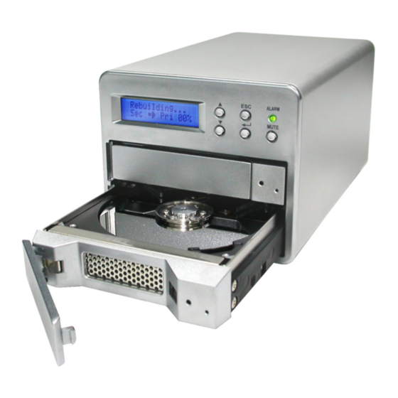
- Page 32 In a few seconds, a correct message will be displayed on screen, and follow by another message indicating automatic reconstruction of data is in progress, as show in illustration. When data is completed, hard-disk will be detected automatically, and a correct message will be displayed.
Need help?
Do you have a question about the SR3610 Series and is the answer not in the manual?
Questions and answers