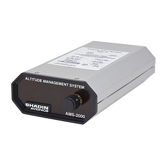
Summary of Contents for Shadin Avionics AMS 2000
- Page 1 AMS 2000, ALTITUDE ALERT SYSTEM PRODUCT P/N: 8900 INSTALLATION MANUAL REV M Shadin Avionics 6831 Oxford Street St. Louis Park, MN 55426 Sales: (800)-328-0584 Technical Support: (800)-388-2849 www.shadin.com MANUAL P/N: IN8900A...
-
Page 2: Table Of Contents
IN8900A Shadin Avionics File: IN8900AMG.doc Directory: 8900 INSTALLATION MANUAL AMS 2000, ALTITUDE ALERT SYSTEM Rev M Page i of ii P/N 8900 PAGE CONTROL CHART SECTION. DESCRIPTION PAGE 1. OVERVIEW The Manual Product Description Specifications 2. INSTALLATION PROCEDURE Unpacking and Inspecting Equipment... - Page 3 IN8900A Shadin Avionics File: IN8900AMG.doc Directory: 8900 INSTALLATION MANUAL AMS 2000, ALTITUDE ALERT SYSTEM Rev M Page ii of ii P/N 8900 REVISION LOG REV. DATE APP’D DESCRIPTION 8-11-00 Baseline release of separate Install Manual 10-30-00 Changed Installation Altitude Management System 4089-023, -026, -024...
-
Page 4: Overview
AMS 2000 does not act as an auto pilot, or control the aircraft in any way. Think of it as an assistant to you, the pilot, which keeps track of minor details and frees you to fly the aircraft. -
Page 5: Specifications
IN8900A Shadin Avionics File: IN8900AMG.doc Directory: 8900 INSTALLATION MANUAL AMS 2000, ALTITUDE ALERT SYSTEM Rev M Page 1-2 P/N 8900 Specifications Physical Specifications Size 1.5 x 3.125 x 5.75 (inches) Weight 0.8 lbs Electrical and Functional Power 14 to 28 VDC 150 mA max... -
Page 6: Installation Procedure
The article may be installed only if performed under 14 CFR part 43 or the applicable airworthiness requirements. The AMS 2000 should be installed in accordance with the standards established by the customer’s installing agency and existing conditions, as to unit location and type of installation. -
Page 7: Electrical Installation
Page 2-2 P/N 8900 Electrical Installation The AMS 2000 will operate with an input range from 14 to 28VDC. Refer to the attached interconnect drawing 4089-023. The installing facility will supply and fabricate all external cables. The required connectors are included in the install kit. The length and routing of external cables must be carefully measured and planned before the actual installation is attempted. -
Page 8: Calibration
Rev M Page 2-3 P/N 8900 The AMS 2000 can be selected to receive Gray code or serial data input. Use Jumper S3 to select serial or Gray code input as indicated (See figure 2-1). Serial option - In Serial mode Pin 14 is the RX, RS-232 communication line that is used to receive serial data from the encoder (8800-X) or Serializer (9200-X). -
Page 9: Post Installation Test Procedure
IN8900A Shadin Avionics File: IN8900AMG.doc Directory: 8900 INSTALLATION MANUAL AMS 2000, ALTITUDE ALERT SYSTEM Rev M Page 2-4 P/N 8900 Post Installation Test Procedure 1. Verify proper jumper selection per drawing 4089-024. 2. Aircraft power on. 3. Refer to Operation Guide to verify operation of 30 second self test. -
Page 10: Environmental Qualification Form
IN8900A Shadin Avionics File: IN8900AMG.doc Directory: 8900 INSTALLATION MANUAL AMS 2000, ALTITUDE ALERT SYSTEM Rev M Page 3-1 P/N 8900 3. ENVIRONMENTAL QUALIFICATION FORM RTCA/DO-160B Certification Conditions Section Categories Temperature & Altitude Temperature Variation Humidity Operational Shocks – Vibration P, K, S... -
Page 11: Installation Drawings And Install Kits Parts Lists
IN8900A Shadin Avionics File: IN8900AMG.doc Directory: 8900 INSTALLATION MANUAL AMS 2000, ALTITUDE ALERT SYSTEM P/N 8900 SECTION 4. INSTALLATION DRAWINGS AND INSTALL KIT PARTS LISTS... - Page 15 Shadin File Name: IK8900AP.DOC DIRECTORY: IKXXXX Report: 4089 Date: January 20, 1997 ECO # 9701/016 Rev: ECO date: 2-20-97 Sec.: Approved: Page 1 of 1 PARTS LIST Part #: IK8900 Drawing #s: N/A Description: INSTALL KIT ALT MANAGEMENT SYSTEM QTY. DESCRIPTION MFG.

Need help?
Do you have a question about the AMS 2000 and is the answer not in the manual?
Questions and answers