Advertisement
Quick Links
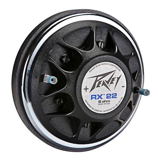
RX™ 22/22XT Replacement Kit Instructions
Instructions for Use with RX 22
Before continuing, make sure this package contains the following:
•
One (1) ferrofluid filled packet
•
This instruction sheet/ Material Safety Data Sheet
•
RX 22 replacement diaphragm
•
XT Spacer Shim (for use with 22XT only)
•
8-32 screws (for use with 22XT only)
Instructions for 22XT+™ Diaphragm
Replacement Kit
These instructions are broken into three sections:
1. Driver Inspection, 2. Diaphragm Replacement
Procedure, 3. Failure Analysis. In most cases, following
this order will assure your success.
*Interchangeable with all Model 22A and Model 22
Drivers.
DRIVER INSPECTION
1. Driver Dead: With an Ohm meter (or in a pinch, a
flashlight battery), determine if the driver is open circuited
by measuring at the driver terminals. D.C.
resistance should be in the range of 4.25 Ohms to 4.75
Ohms. Unless you have a precision-calibrated meter
or a bridge, consider the driver to be okay if you're in
the ballpark. If using a battery, no "click" when connecting
and disconnecting the battery means the driver
is open.
Figure A
GAP
LOCATING PIN
FRONT PLATE
HOLE
Figure B
Cover Assembly
GASKET
LOCATING PIN
SUSPENSION
DIAPHRAGM
Logo referenced in Directive 2002/96/EC Annex IV
(OJ(L)37/38,13.02.03 and defined in EN 50419: 2005
The bar is the symbol for marking of new waste and
is applied only to equipment manufactured after
13 August 2005
:
2. Driver Noisy or Distorted: If you have a sine wave
oscillator, sweep the driver with 4 Volts from 500 Hz to
2,000 Hz. Any buzzing or distortion will indicate that
the diaphragm must be removed. An intermittent noise
could be a metal particle in the gap. Check the gap
carefully and clean before you replace the diaphragm
to rule out this possibility. A flashlight is a great help. If
an oscilloscope is available, look at the waveform at
the driver to rule out an electronic malfunction if high
distortion is your symptom.
DIAPHRAGM REPLACEMENT PROCEDURE
(see Figures A and B on reverse side)
1. Clean the front plate and environment of all metal
particles.
2. Remove the six 8-32 screws holding the diaphragm
assembly to the front plate. These will be replaced with
a longer screw, included (71500875).
3. Remove the failed diaphragm assembly to a safe
place to prevent damage so that we can inspect it.
(You might want to look closely at it, too.) Please return
the failed diaphragm assembly to your dealer or
directly to Peavey using the box in which the new
LOADING
assembly arrived. Describe the operating conditions
PLUG
surrounding the failure with as much detail as possible.
This information will help immeasurably in improving
the performance of our products.
4. Fold a piece of 3/4" wide masking tape into a triangle
shape with the adhesive side out. Using a flashlight
to see into the gap in the magnet structure, slide tape
around the entire gap to clean out all metal chips and
dirt.
5. Install the included XT spacer shim.
6. Make certain the rubber gasket is properly seated
on the new cover assembly, exposing the entire aluminum
ring. The ring must sit flat on the front plate
when in place.
7. By eye, line up the locating pins on the cover with
the untapped holes on the front plate. These holes are
SCREW HOLE
easy to locate since they are between tapped holes for
the 8-32 screws. If the gasket will not stay on the
cover, tilt the driver past vertical and let gravity help
you.
8. Gently push the diaphragm assembly onto the driver,
making certain that the locating pins are going into
their holes.
9. With the cover in place, carefully check the gasket
to be sure it hasn't slipped under the ring. (If it has,
start over or use tweezers to reposition the gasket.)
10. Now that you have assured yourself that the
diaphragm assembly is seated solidly on the front
plate, put the new, longer 8-32 screws into the holes
and tighten. A tightening sequence is not necessary.
VOICE COIL
Note: The XT spacer shim (gasket) is only used
on the 22XT+ and all other older 22 drivers.
RX22 does not use the spacer.
Note: While a necessary component for the RX
22, the ferrofluid is optional for the 22xt+ kit.
Using the ferrofluid, however, would be an
added benefit for the 22xt+ kit, by reducing the
heating of the voice coil, improving the power
rating and smoothing the frequency response in
the mid region of the driver.
Peavey Electronics Corporation • 5022 Hartley Peavey Drive • Meridian, MS 39305
Phone: (601) 483-5365 • Fax: (601) 486-1278 • www.peavey.com •
Procedure:
Remove the diaphragm assembly from the driver by removing the six screws in the top cover.
1)
2)
Remove the old ferrofluid by inserting a strip of filter paper into the gap, allowing it to sit for one (1) minute. Remove the strip
and repeat the process using a fresh piece of paper until no ferrofluid remains in the gap. If you run out of filter paper, any absorbent
paper can be used to complete the job.
3)
Inspect the magnetic air gap for the presence of any debris. If necessary, clean the gap with a piece of folded masking tape
(sticky side out).
4)
Using the notch in the side of the packet as a locating guide, unscrew the fluid-filled bottle. Pour out the contents of the bottle
into the magnet structure gap.
Note: It is not necessary to rotate the magnet; the ferrofluid is self-distributing. Attempting to dispense the remaining ferrofluid
may over fill the air gap, which has no benefit.
Note: Remove and discard the enclosed Spacer Shim if using the RX22.
Replace the diaphragm assembly and firmly tighten the six screws. Word of advice: When tightening the screws try to tighten
5)
them down evenly, the same amount as you go around the cover. This will help eliminate any mechanical distortion in the
diaphragm. Thank you for choosing Peavey as your musical instrument supplier.
80302569 • ©2007 Printed in the U.S.A.
FAILURE ANALYSIS
You may be able to learn why your driver failed by
inspecting the failed diaphragm assembly. We powertest
and rigorously analyze each diaphragm assembly.
Consequently, there is more than an even chance
that the diaphragm assembly failed because of too
much power input.
1. The voice coil is copper in color initially and turns
dark brown, even black, under hard use. This is due to
a color change in the epoxy adhesive on the wire
(occurs at 300° F).
Any charring on the wire is a sign of too much power.
If some turns have come off the coil and the wire is
shiny, most likely the coil was rubbing on the gap walls
before failure.
2. Diaphragm Broken, Cracked or Dented: When
the driver is driven with high amplitude, low frequency
signals at or below the low frequency limit of 500 Hz,
the diaphragm bottoms on the loading plug, causing
the above mentioned damage; also, input power
above the design limit within the passband of the driver
can cause this damage.
3. Determining Power Input to the Driver: This is an
extremely difficult proposition with program material
even with very sophisticated measuring instruments.
The formula that applies is power=(voltage x voltage)
/ impedance. Assume the impedance listed on the
diaphragm assembly label and use either a calibrated
oscilloscope or Voltmeter to determine Voltage. The
driver is capable of withstanding many times rated
power for short duration but average long term power
(measuring RMS Voltage) is 40 Watts. If your amplifier
is oscillating or your P.A. is operated in feedback,
unusually high Voltage could be applied to the driver
causing failure.
We appreciate your interest in our product; if you
require further assistance, please contact your dealer
or our factory.
*see Ferrofluid Safety Information on Reverse side of this
sheet.
Advertisement

Subscribe to Our Youtube Channel
Related Manuals for Peavey RX 22


Summary of Contents for Peavey RX 22
- Page 1 DIAPHRAGM Logo referenced in Directive 2002/96/EC Annex IV Peavey Electronics Corporation • 5022 Hartley Peavey Drive • Meridian, MS 39305 (OJ(L)37/38,13.02.03 and defined in EN 50419: 2005 The bar is the symbol for marking of new waste and Phone: (601) 483-5365 • Fax: (601) 486-1278 • www.peavey.com •...
- Page 2 Ferrofluid Material Safety Data Sheet PRODUCT IDENTIFICATION SPILL OR LEAK PROCEDURES Manufactured by: Ferrofluidics Corporation Steps to be taken in case material is released or spilled: Remove free liquid. Add 40 Simon St. absorbent (sand, earth, sawdust) to spill area. After removing absorbent, wash Nashua, NH 03061 surface with soap and water to reduce possible slipping hazard.
Need help?
Do you have a question about the RX 22 and is the answer not in the manual?
Questions and answers