Table of Contents
Advertisement
Advertisement
Table of Contents

Subscribe to Our Youtube Channel
Summary of Contents for Antec controls VENTURI FX
- Page 1 VENTURI FX MANUAL v106...
-
Page 2: Table Of Contents
General ......................................1 Safety Precautions ..................................1 Product Overview ..................................2 Technical Specifications ................................2 Airflow Ranges ....................................2 GETTING STARTED WITH THE VENTURI FX (VFX)..........................3 Receiving Inspection ..................................3 In the Box ......................................3 Construction Options ..................................4 INSTALLATION & MOUNTING INSTRUCTIONS ..........................6 Installing the Venturi FX (VFX) Valve .............................6 VALVE ACCESSORIES ..................................8... -
Page 3: Introduction
INTRODUCTION General In this manual, you will find information regarding: CAUTION • Venturi FX (VFX) specifications • How to install the VFX with Constant Volume, Variable This mark indicates an important point for Volume, and Two Position Switch the proper function of the VFX and any of its •... -
Page 4: Product Overview
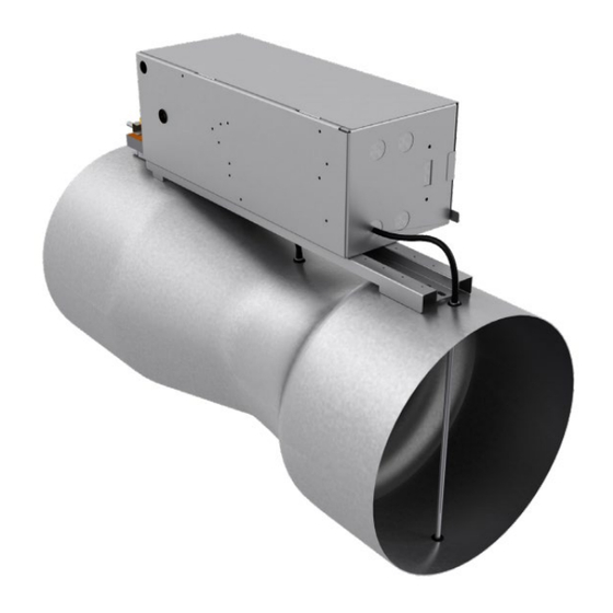
VFX - MANUAL Product Overview The Antec Controls Venturi FX Valve (VFX) is designed specifically for room pressure control in healthcare and laboratory applications. Paired with the maintenance-free, high accuracy Antec Controls Pressure Transducer (PTX) or the Pace™ Critical Space Controller (PACE) and an actuator, the VFX achieves precise airflow measurement and control for critical environments. -
Page 5: Getting Started With The Venturi Fx (Vfx)
VFX - MANUAL GETTING STARTED WITH THE VENTURI FX (VFX) Receiving Inspection After unpacking the assembly, check carefully for shipping damage. If any damage is found, report it immediately to the delivering carrier. Damage may result from improper handling. CAUTION Do not tamper with the linkage assembly as the valve is shipped factory calibrated. -
Page 6: Construction Options
Construction Options Below is an outline of some of the key options that are available when selecting and ordering Venturi FX (VFX). These options will affect its available flow range, how the valve is installed and under what system conditions it must operate. - Page 7 VFX - MANUAL Coating The Venturi FX is available in four different protective coating options depending on the application. Aluminum Model: VFX-AL Features: Aluminum valve body with Stainless Steel (SS) internal hardware NOTE: Can be mounted using sheet metal screws.
-
Page 8: Installation & Mounting Instructions
3/8 in. 3/8 in. Enclosure Orientation Venturi FX controls enclosures may be rotated 360 degrees around the ductwork. Enclosure Orientation In fume hood applications, or in conditions that may cause condensation inside the ductwork, the enclosure should not be mounted within +/- 90 degrees from straight down. - Page 9 VFX - MANUAL Slip-Connection Venturi FX (VFX) Mounting Instructions The instructions below are detailed for Aluminum VFXs only. Do not use screws for Phenolic coated valves. STEP 1 Mount the VFX by slipping both the inlet and the discharge one inch (1”) into the appropriately sized ductwork.
-
Page 10: Valve Accessories
VFX - MANUAL VALVE ACCESSORIES Venturi FX (VFX) can function with a variety of different products to control air temperature, decrease noise and improve ease of installation. Valve Accessories and Optional Products provided by Antec Controls include: CAUTION Hot Water Coils (VVHWC) - Page 11 Installation STEP 1 Hot Water Coils are only available in supply orientation and should always be located down stream of the supply Venturi FX. STEP 2 For single VVHWCs, position the bead connection so that it faces the airflow. For multibody VVHWCs, position the slip connection so that it faces the airflow.
-
Page 12: Electric Coils (Vvec)
VFX - MANUAL Electric Coils (VVEC) Electric Coils (VVEC) are devices installed with Venturi FX that control room environment by heating the air moving through the valve. The VVEC operates using standard building electrical power and is designed to optimize heat transfer. - Page 13 Mechanical Installation STEP 1 Electric coils are only available in supply orientation and should always be located down stream of the supply Venturi FX (VFX). STEP 2 Use the support method prescribed for the duct work in the job specifications.
-
Page 14: Silencer (Vvsil)
VFX - MANUAL Silencer (VVSIL) The Silencer (VVSIL) is a highly engineered 14-inch silencer specifically designed for the full spectrum attenuation of sounds produced by Venturi FXs (VFX). The packless design provides minimal disturbance in the airflow resulting in low pressure drops across the silencer. -
Page 15: Valve Companion Connections (Vct)
Drawband clamps allow for quick installation or removal of the Venturi FX while minimizing damage from metal screws. Companion flanges are available for single body valves. Companion flanges are to be slid onto duct with a 1.5-inch overlap and mechanically fastened to the valve flange. - Page 16 VFX - MANUAL Slip-Connection Venturi FX (VFX) with Drawband Clamps Installation STEP 1 Slide drawband clamps completely onto the inlet and discharge ductwork. STEP 2 Mount the VFX by slipping both the inlet and the discharge one inch (1”) into the appropriately sized ductwork.
- Page 17 VFX - MANUAL Flange-Connection Venturi FX with Companion Flanges Installation STEP 1 Slide companion flanges completely onto the inlet and discharge ductwork with the flanged end of the companion flanges toward the free space. STEP 2 Align hole pattern to match opposing companion flange.
-
Page 18: Valve Installation Tape (Vit)
VFX - MANUAL Valve Installation Tape (VIT) Valve Installation Tape (VIT) is used during installation of the Venturi FX in corrosive applications and is wrapped around the valve and ductwork connection to ensure an airtight seal. Overview See the VIT Product Submittal on AntecControls.com... -
Page 19: Valve Actuator
Valve actuators are wired into the valve controller and are attached to the linkage bars of the valve. The actuator controls the position of the blade damper inside of the Venturi FX which controls the amount of air that flows through the valve. Valve actuators come in two main options: Standard Speed and High Speed. -
Page 20: Balancing
Variable Volume VFX Adjustments to the flow reading can be made by adjusting the Kfactor. NOTE: When using PACE or CAVA controllers from Antec Controls, please refer to the appropriate manual for instructions on adjusting the settings described below. Kfactor The Kfactor is a multiplier that is applied to the controller’s differential pressure reading. -
Page 21: Troubleshooting
VFX - MANUAL TROUBLESHOOTING Venturi FX Troubleshooting Symptoms Possible Cause Foreign material in valve Noise Vibrating duct work Confirm that power is being delivered to the unit Verify control signal Actuator Does Not Operate Verify that the disconnect switch (where available) is not open... -
Page 22: Replacement Parts
VFX - MANUAL Replacement Parts Replacement parts are available. Please contact your local Antec Controls Representative. Technical Support If technical support is required, please contact us: By Email: Applications@AntecControls.com By Phone: 866.884.3524 Hours of Operation: Monday – Friday, 8:00 AM to 4:30 PM CT NOTE: If you will need support after hours, please contact us 48 hours in advance. - Page 23 Limited Warranty. The complete product catalog can be viewed online at AntecControls.com ® Antec Controls by Price is a registered trademark of Price Industries Limited. © 2022. Printed in Canada. v106...
Need help?
Do you have a question about the VENTURI FX and is the answer not in the manual?
Questions and answers