Table of Contents
Advertisement
Quick Links
Advertisement
Table of Contents

Summary of Contents for ABB F4HC
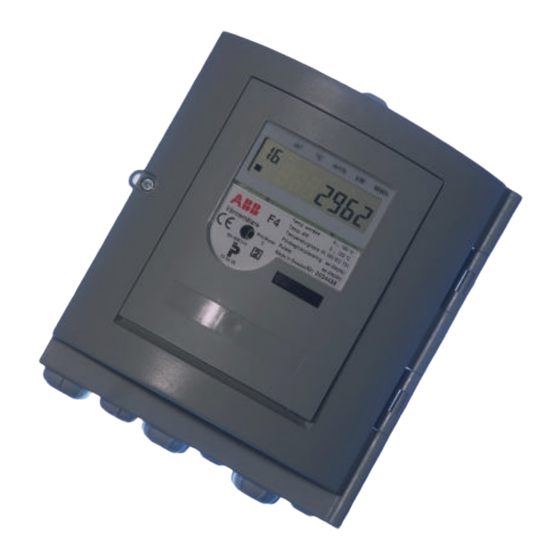
- Page 1 Calculator F4HC Manual addition...
- Page 2 Calculator F4HC Manual addition 3.3.5.1 Display Sequence Normal mode 3.3.5.1 Display seq. Normal Mode 2 5.2.1.1 EN1434 terminal table 5.2.2 Pulse input connection 7.3 Service 7.3.0 Time 7.3.1 Date 7.3.4 Account days 7.3.6 Communication address 7.3.7 Resetting stored error time 7.3.8...
- Page 3 Manual addition This is only a manual addition with the differences to the standard F4 calculator.
-
Page 4: Display Sequence Normal Mode
3.3.5.1 Display Sequence Normal mode Description Accumulated energy. Heating (Default pos ition) Accumulated volume. Heating Accumulated energy. Cooling Accumulated volume. Cooling Display test, see fig.3.2 Error Code, see Error code Accumulated Error Time, [Mi nutes] Pulse counter 1 Momentary Power [H/C] Momentary Flow Supply Temperature (High) Return Temperature (Low) -
Page 5: Display Seq. Normal Mode
Display seq. Normal Mode 2 ID Option card A Status option card A ID Option card B Status option card B ID Option card C Status option card C ID Option card D Status option card D ID Option card E Status option card E ID Option card F Status option card F... -
Page 6: Sensors And M-Bus Connection
5.2.1 Sensors and M-Bus connection The connection of temperature sensors are shown in figure 5.2 and table 5.1, according to EN1434. Warning:Do not connect the M-Bus to the wrong 5.2.1.1 EN1434 terminal table terminal or the meter can be seriously damaged when the M-Bus loop is Termi powered. -
Page 7: Pulse Input Connection
5.2.2 Pulse input connection The calculator can accumulate pulses from other meters, such as electricity meters, cold and warm water meters and gas meters. Pulse input shall be connected to the terminal marked IN and the outputs from the other device shall be of the type “Open Collector”. - Page 8 By changing the value to “0” necessity to change the parameter setting within the will reset the stored error time. meter. Some parameters can be changed in the F4HC meter without the “Service program” version “FxHC”. Following service procedure 7.4.8 Placement of flow sensor...
-
Page 9: Technical Data
8. Technical data Data output table Following data is accessible via the data output: Manufac 60870-5 ture SIOX Data (Option Specifi Flow sensor placing Program version Manufacturer Communication address Meter number Error code (limited) Accumulated energy Accumulated, volume 1 Accumulated, volume 2 Flow temperature (high) Return temperature (low) Temperature difference... - Page 10 © ABB Metering AB Kista, Sweden Date : 2001-01-15 Created by: Johan Tsung Rev. date: 2001-05-29 Rev. by: Göran Walmstedt Filename : F4 Manual [3-4-01 ME].doc Revision no.: 1.031 _______________________________________________________________________________________ ABB Metering AB +46 8 632 96 00 Tel.: e-mail / Web: Doc.name:...
Need help?
Do you have a question about the F4HC and is the answer not in the manual?
Questions and answers