
Related Manuals for AALogic Snoopy SR-101


Summary of Contents for AALogic Snoopy SR-101
- Page 1 SR-101 Signal Receiver Fault Location Identification Receiver Technician Manual Version 2.0.0...
- Page 2 Allied Analogic. Inc. 132 Redtail Ct. Weatherford, TX 76088 (817) 599-0272 © 2017, AALogic Inc., All rights reserved...
-
Page 3: Table Of Contents
Table of Contents General Description ..........................1 Features ............................1 Probe Compatibility ........................1 How Fault Locating Works ......................1 Training ............................1 What is included ........................... 2 Main Display ............................2 Modes ..............................2 CheckDSL ............................3 Buried ............................3 Aerial ............................. -
Page 5: General Description
The ST-101 transmitter sends a high voltage, low current signal that is compatible with receivers capable of monitoring one of the signal frequencies. 1.4 T RAINING Check www.AALogic.com for videos or contact your local representative for additional information on the SR-101 Receiver and other AALogic products. Version 2.0.0... -
Page 6: What Is Included
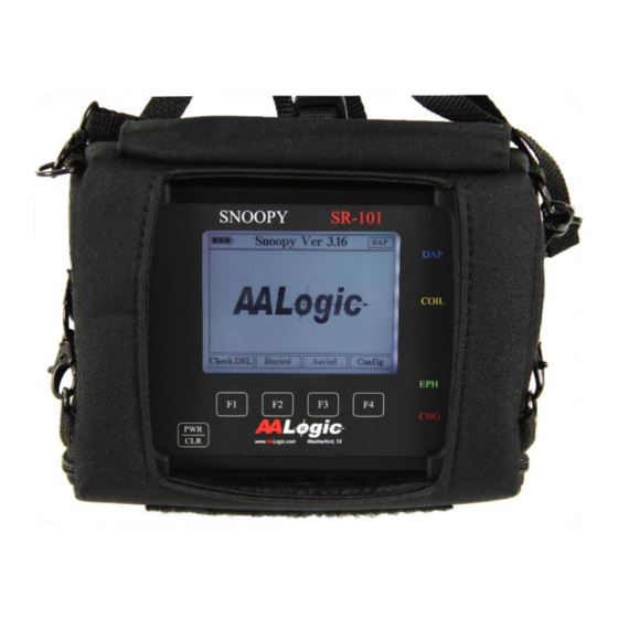
HAT IS INCLUDED The SR-101 includes the following: • SR-101 Signal Receiver • DAP-125 Differential Amplifier Probe • DHC-124 Differential Hand-coil Sensor • Carrying case • Charger • USB Drive with manual ISPLAY The SR-101 main display is shown in the following picture. •... -
Page 7: Checkdsl
101, must be used to send tone on the fault. This mode can also be used to monitor 577Hz and 987Hz pair identification tone sent by AALogic or other manufacturer test sets. The DAP-125 is connected to the SR-101 for pair identification. -
Page 8: Display Setup - Contrast And Backlite
5.2 D – C ISPLAY ETUP ONTRAST AND ACKLITE Press the [F4] Config key from the main screen to display the Config screen. You can adjust the display for personal preferences. The Contrast and Backlight levels are both adjustable. It may be easier to increase the backlight to a comfortable level first and then adjust the contrast. -
Page 9: Carry Case
This timeout can be set in 15-minute increments from OFF to 45 minutes, as shown, the SR-101 remains on until the user turns it off with the [PWR/CLR] or the battery is exhausted. Press the [F2] ↓ and [F3] ↑ keys to decrease or increase the value and press [F1] Select to save the setting. -
Page 10: Aerial Mode
ERIAL The Aerial mode uses a high-gain audio monitor to display signal levels. A time-based graph is displayed providing a history of signal strength along with a matching audible tone. The graph is extremely useful when analyzing signal level changes as the sensor is moved over the cable. The graph records from left to right and takes approximately 20 seconds to complete the initial pass. -
Page 11: Pair Split
• Tip or Ring of one pair is split with the Tip or Ring of another pair Split ✓ Locating ground faults are more difficult due to multiple ground signal return paths. It is recommended to locate shorts or crosses whenever possible. Otherwise it may be helpful to remove shield ground at the transmitter location, then connect the transmitter leads to the faulted wire and shield. -
Page 12: Dhc-124 Differential Hand-Coil Sensor
6.3.1 Other Probes and A-Frame A phone plug connector on the right side of the SR-101 allows using other compatible probes with the SR- 101. Probes not manufactured by AALogic may not be compatible. DAP-125 or DHC-124 connection jack. A-Frame and other probes. -
Page 13: Locating An Aerial Fault
6.4 L OCATING AN ERIAL AULT A signal transmitter, such as the ST-101, must be connected to the fault as discussed in 6.2 above. The frequency and power settings for the transmitter should be selected and the transmitter set to send. Refer to the transmitter documentation as needed. - Page 14 Select the frequency matching the transmitter frequency. Use [F1] Select if needed to highlight Freq on the screen. Use [F2] ↓and [F3] ↑ to highlight the desired frequency. The Frequency is immediately changed each time [F2] or [F3] is pressed. Place the probe near the cable and adjust the Gain and Volume for adequate signal indications on the SR-101 and from the speaker/earphone.
-
Page 15: Detecting Dsl
Note: The cable pair and group are twisted inside the cable. This means the pair may be on the top, bottom, or middle as the probe is moved along the cable. It is normal for the signal indication to rise and fall wile monitoring the cable. The fault location is determined by higher average signal peaks before the fault than after the fault for shorts and crosses. -
Page 16: Circuit Id
7.2 C IRCUIT The Circuit ID function scans a number of frequencies to determine the type of DSL signal on the pair if one is present. The types of DSL detected are HDSL, T1, ADSL, or VDSL. The indication xxDSL is displayed when an unknown DSL type is detected. -
Page 17: Specifications
PECIFICATIONS Receiver Gain ≥ 90dB DAP-125 Gain 40dB DHC-124 Gain 12dB Display Transflective Sunlight Readable Backlight Resolution 320x240 Power Li-ion 2000mAH Charger 6Vdc@1.0A Operate Time 8 to 16 hours Charge Time Approximately 2 Hours Temperature Charge 0 to 45c (32 to 113F) Operate -20 to 60c (-4 to 158F) Storage... - Page 18 THIS PAGE INTENTIONALLY LEFT BLANK. Version 2.0.0...
Need help?
Do you have a question about the Snoopy SR-101 and is the answer not in the manual?
Questions and answers