
Related Manuals for insize ISP-A5000


Summary of Contents for insize ISP-A5000
- Page 1 MN-ISP-A5000/A5000E-E www.insize.com ISP-A5000/A5000E PROFILE PROJECTOR OPERATION MANUAL...
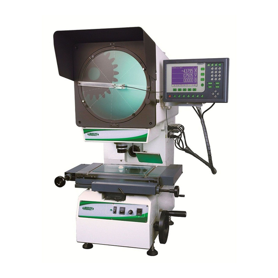
- Page 2 Description Key functions: 1. LCD Display 2. Soft Keys 3. LCD Standby On / Off Key 4. Feature Measurement Keys 5. Help Keys 6. Arrow Keys For Navigation 7. Utility Keys 8. Numeric / Function Keys 9. Coordinate And Unit Switch Buttons 10.
- Page 3 The surfaces of optical parts should be kept clean. They should not Cross Hair measurement be touched with hands. If any dirt, oil fleck or dust are found on the Automatic Edge Detector measurement (ISP-A1000E) surfaces, they should be removed with soft brushes, or they should Counter clock wise direction be removed with clean linen or lens paper soaked in methyl benzol Clock wise direction...
-
Page 4: Maintenance
Back panel: Point Tolerance: Highlight the desired point feature from the result list. Press } key and then Press { } key. Enter the nominal values for X and Y co-ordinates. Also enter the tolerance zone. Tolerance zone is the radius within which the point should be 1. - Page 5 Cross hair and mounted edge detector probe may have physical position offsets, hence to obtain accurate results; we must do the cross calibration process for every magnifications. If we don’t execute cross cal, and if we probe a circle by cross hair and by edge detector, in both cases, we will get diameter equal but centre coordinates will be different.
-
Page 6: Axis Calibration
Set Factory Settings: All the engineering settings are set to Screen Gain (<10000) – This sets the gain of the amplifier. The factory default parameters. gain depends on the magnification and the light source. Adjust this such that the Screen intensity on light region displays counts Configure Footswitch: Enables the user to assign any key from above 3000 counts to 4000. - Page 7 Linear Error Correction(L.Comp/LEC): DRO mode press { } key to enter Edge detector calibration. In this mode place a slip gauge of standard length on the X-Y Following screen will be displayed. table. Align it properly for calibration. Now bring cross hair to one of the edge of slip. Reset the axis. Now move the crosshair to other end of the slip and note down the display reading.
- Page 8 Calibration Procedure: Perform Machine reference in the axis settings. After performing machine reference do not set or reset the axis till the complete SLEC calibration is complete. Divide the travel into user defined segments. Enter into standard measurement mode (DRO mode). Note down all the standard values and the observed values for each segment.
-
Page 9: Machine Reference
The changes will get saved in the memory and are applied. The user will have to perform machine reference on every power ON if SLEC is selected for an axis. Grid Calibration: It is also referred to as Non Linear Error correction (NLEC). In this the entire measurement area is divided in to a grid. - Page 10 Calibration Procedure: Keep the encoder position near to the desired reference on the encoder. P r e s s { } k e y i n “ M a c h i n e R e f . ” i n a x i s s e t t i n g s . “Homing”Message is shown on the screen.
- Page 11 Press key which displays the list of measured features. Measurement Point Measurement: Press [ ] key to measure a point. Now move the X-Y table near to the desired point. Match cross hair on the point and press [ ] key. Take more points or if sufficient points are taken press [ key.
- Page 12 Now target a point on the circle and match cross hair on it. Result Buffer View: Press [ ] key. To view a results measured press { } key. A graphical view of results will be displayed. Use up-down arrow keys to move next Now in similar manner probe sufficient points to form a best fit or previous results one by one or press { } key to recall...
- Page 13 Skewing the job is also possible from constructed features. The result of constructed feature should a line, since skew is applied on a probed line. For example, if a line is constructed from a circle and a line. The result line is the skewed line. And all the measurements are with respect to this line.
- Page 14 Now probe line which is to be skewed. Use standard procedure for line measurement. Probing more points will increase the accuracy of skew measurement. Press [ ] key to complete skew measurement. The result s c r e e n i s d i s p l a y e d a s s h o w n b e l o w. A n y f e a t u r e measurement done henceforth will be with respect to skewed Skewing the Job: co-ordinates.
Need help?
Do you have a question about the ISP-A5000 and is the answer not in the manual?
Questions and answers