Table of Contents
Advertisement
Advertisement
Table of Contents

Subscribe to Our Youtube Channel
Summary of Contents for Generac Power Systems 21-light
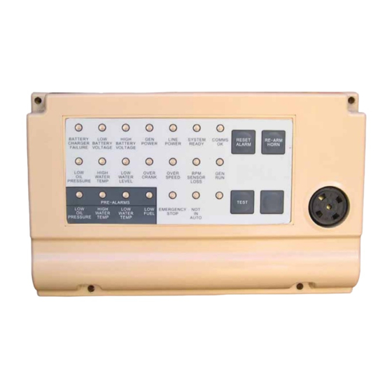
- Page 1 21-light Remote Annunciator O w n e r ’s M a n u a l...
-
Page 2: Table Of Contents
Remote Annunciator Annunciator Description ..Inside Font Cover System Keypad Switches ........5 Detailed Specifications ........1 Test Switch ................. 5 Environmental Specifications ..........1 Re-arm Horn Switch ............5 Power Supply Requirements ..........1 Reset Switch ............... 5 Communication With Generator Control System ....1 Spare Keypad Switch ............ -
Page 3: Detailed Specifications
Remote Annunciator Figure 2 — Location of DIP Switches, RS232 Connector & JMP1 JUMPER BETWEEN 1 & 2 = RS485 TERMINATING RESISTOR IN CIRCUIT JUMPER BETWEEN 2 & 3 = TERMINATING RESISTOR OUT OF CIRCUIT JUMPER MISSING = TERMINATING RESISTOR OUT OF CIRCUIT RS232 DB9 CONNECTOR USED WITH THE JMP1... -
Page 4: Installation And Mounting
Remote Annunciator INSTALLATION AND MOUNTING RELAY ANNUNCIATION (J1 - J8) NOTE: The user can select up to eight of the following 18 generator parameters to annunciate via the relays, when the 10 position (S1) 3. For ALL models installation must always comply with and the 8 position (S2) DIP switches on the annunciator PCB are applicable codes, standards, laws and regulations. -
Page 5: Parameter Selection Examples
Remote Annunciator Figure 4 — DIP Switch S1 Settings Figure 7 — S2 Figure 5 — DIP Switch S2 Settings Example 2 If subsequently DIP1-3 is removed, and DIP2-5 is added, then relays will be re-assigned (Figures 8 and 9). Parameter Relay 1, 1... -
Page 6: Parameter "Generator Run
Remote Annunciator PARAMETER "GENERATOR RUN" GENERATOR STOP INDICATORS These lights/LEDs will flash when any alarm occurs and the horn This parameter is defined as any one or more generators in the will sound as follows: system running. Annunciator Light Light Color Audible Alarm PARAMETER "GENERATOR POWER"... -
Page 7: Spare Indicator
Remote Annunciator These alarms will be latched/not latched by the annunciator COMMUNICATION OK according to the above table. They can be acknowledged at the This LED will be ON as long as there is proper communication annunciator using the ‘Reset' switch— the active lamps will then between the Remote Annunciator Panel and the Generator control stop flashing and remain in the ON state until the alarm signal system. -
Page 8: Spare Keypad Switch
Remote Annunciator NOTE: Figure 11 — Annunciator’s connected to a System Controller (SC) and Multiple G-panels 12. Pre-alarm conditions MUST be reset at the generator set control panel. SPARE KEYPAD SWITCH Annunciator PM-SC When DIP Switch S3, Position 4, is in the ON position, it allows the (Slave) (Master) SPARE Keypad Switch to control Relay 8. -
Page 9: Alarm Relay (J9)
Remote Annunciator ALARM RELAY (J9) Shown in Figure 12 is a typical Windows GUI interface as it appears on the computer display. The Annunciator provides a relay with both a Normally Open con- tact and a Normally Closed contact. This relay is energized when RS485 COMMUNICATIONS DC power is provided to the Annunciator so that in the event power In a typical application, the Annunciator monitors (i.e. -
Page 10: Error Handling
Remote Annunciator ERROR HANDLING TERMINOLOGY & ABBREVIATIONS An error will be reported by flashing the Communication OK light— - Graphical User Interface for Windows based comput- the rate of flashing will be indicative of the cause of the error. 1. No reply from generator control system— frequency one sec- - Modular Power System ond on/one second off. -
Page 11: Troubleshooting Guide
Remote Annunciator TROUBLESHOOTING GUIDE No Lights/LEDs are Lit. 1. Check for the proper battery supply at terminal block J10 pins 1 and 2. • J10 pin 1 should be + Battery (12 or 24 volts). • J10 pin 2 should be – Battery. •... - Page 12 Part No. 0G6960 Revision C (09/ 14/ 09) Printed in U.S.A.
Need help?
Do you have a question about the 21-light and is the answer not in the manual?
Questions and answers