
Related Manuals for Krohn-Hite 522


Summary of Contents for Krohn-Hite 522
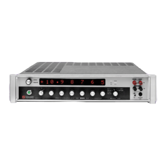
- Page 1 Model 522 Manual/Remote Controlled (GPIB Programmable) DC Voltage/Current Calibrator Operating Manual...
- Page 2 This page intentionally left blank.
- Page 3 PROGRAMMABLE VOLTAGE CALIBRATOR CURRENT Model 522 Serial No.______________ Win-man\522.wpd...
- Page 4 OPERATORS MANUAL Copyright © 1999 Electronic Development Company Division of KROHN-HITE 15 Jonathan Drive Unit 4 Brockton, Massachusetts 02301 E-mail: Info@krohn-hite.com www.krohn-hite.com All rights reserved. No part of this publication may be reproduced, stored in a retrieval system or transmitted in...
-
Page 5: Theory Of Operation
522 TABLE OF CONTENTS SECTION TITLE List of Drawings Limited Warranty Factory Service Request and Authorization Packing Suggestions DESCRIPTION AND SPECIFICATIONS 1.1.0 General Description 1.2.0 Features and Applications 1.2.1 Features 1.2.2 Applications 1.3.0 Output Specifications 1.4.0 General Specifications 1.5.0 Mechanical Specifications 1.6.0... -
Page 6: Parts List
Calibration Procedure OPTIONS - (If Installed) 6.1.0 1 Volt Option RA-7 6.2.0 Calibration. of the RA-7 option. PARTS LIST 7.0.0 Replacement Parts for Model 522 NOTE: Errata and addendum (if any) will appear in the back of this manual. Win-man\522.wpd... - Page 7 1V Range Board Layout - Option RA-7 A-4817 Rev. F System Block Diagram B-4633 Rev. A Power Supply Schematic B-4615 Rev. B 522 Control Board Schematic (Displays ) B-4819 Rev. A 522 Control Board Schematic (Switches) B-4820 Rev. A MPU Board Schematic B-4763 Rev. A DAC Schematic C-4614 Rev.
-
Page 8: Limited Warranty
CAUTION: The instrument you have purchased is a precision instrument manufactured under exacting standards. Any attempts to repair, modify or otherwise tamper with the instrument by anyone other than an EDC employee or authorized representative may result in this warranty becoming void. Win-man\522.wpd... -
Page 9: Warranty & Service
Symptoms, measurements taken, equipment used, lash-up procedures, attempted repairs, suspected location of failure and any other pertinent information. B) Freight Charges must be PREPAID. C) The RETURN AUTHORIZATION NUMBER should be noted on your documentation. See Packing Suggestions - next page. Win-man\522.wpd... - Page 10 Please do not bounce it across the country in a truck. It may not hurt it, but it certainly is not going to do a laboratory instrument much good. QUESTIONS? Just contact us. We will be pleased to help you. Win-man\522.wpd...
-
Page 11: Description And Specifications
1.0.0 1.1.0 General Description 1.1.1 The EDC Model 522 is a microprocessor controlled enhanced version of the field proven Model 521. An industry standard 6500 series microprocessor has been incorporated to improve the reliability, and versatility of the instrument. 1.1.2... - Page 12 Simulation of thermocouple and strain gages. (4 to 20 mA and 10 to 50 mA) and other transducers. NOTE: Compliance voltage from 1V to 100 Vdc. Compliance limits are selectable. Linearity check of amplifiers and function modules. Win-man\522.wpd...
- Page 13 Elimination of "worst case" conditions by implementing carefully monitored, standards laboratory procedures. Stability: (*non-additive) 8 hrs: ±0.00075%; 24 hrs: ±0.001% 90 days: ±0.0015% 1 yr: ±0.002% Line & Load Regulation: (*non-additive) ±0.0005% No load to full load for a ±10.0% line fluctuation Win-man\522.wpd...
- Page 14 Switching and Settling Times: Step Changes: 5 ms Range Changes: 300 ms Protection: Voltage mode: Short-circuit and overload protection. Current mode: Open-circuit protection. Front panel enunciator and alpha-numeric display will indicate malfunction condition. Warm-up Time: 1 hour to rated accuracies Win-man\522.wpd...
- Page 15 Certification: A Certificate of Compliance is issued with each new instrument to certify the calibration traceable to the National Institute of Standards and Technology (N.I.S.T.). Warranty: Full ONE YEAR warranty on parts and labor and a full ONE YEAR warranty on specifications and performance. Win-man\522.wpd...
-
Page 16: Installation
2.0.0 2.1.0 Mounting The 522 is designed for mounting in a standard 19" relay rack. When installing in the rack it is recommended that nylon washers be placed under the mounting screws to prevent scratching the paint. 2.2.0 Mating Connectors All instruments are supplied with a mating AC power cord and output connector. -
Page 17: Operation Of The Instrument
NOTE: When the 522 senses an overload condition the unit will display "OVERLOAD" in the digit display area. When this happens the 522 will reset itself to crowbar and output zero. To return to the current range you must first remove the cause of the overload. Then you must either send more data if you are in remote mode, or turn one of the switches if you are in the local mode. - Page 18 The "load" and "sense" refers to the 4 wire remote sense capability. NOTE: THE "LOAD-SENSE" CIRCUIT MUST BE COMPLETE IN EITHER ONE OF TWO CONFIGURATIONS: (Please refer to Drawing #930727 in the rear of this manual for the two-wire and four-wire connections. Win-man\522.wpd...
- Page 19 However, if an appreciable current is to flow in the circuit, in the voltage mode, i.e, .1 mA, then the sense lines should be connected at the load. (See Figure 1 on Reference Drawing #930727) This 4 wire system eliminates the IR drop and thus maintains the voltage accuracy, of the Model 522, at the load.
- Page 20 RL0, PP2, DC0, DT0, E1, (see para. 3.4.4.1 for PP2 exception). 3.4.2 Setting The Instrument's Listen Address. The EDC 522 is both a "Listener and a limited Talker" instrument. Its address is set with a "dip switch" located on the rear panel.
- Page 21 C. Serial Poll in response to a SRQ. D. Parallel Poll to indicate device status. E. Interface Clear (IFC) 3.4.4 Data Byte String Format. In general, the 522 is programmed with an eight character data byte string. ATN must be false on these bytes. CHARACTER...
- Page 22 National's Lab Windows driver for the 522 is available on request. NOTE: the 522 should see an eight, (8) character word for correct programming. It will act on the first 8 bytes. The 522 must receive an end of message terminator to act on the message.
-
Page 23: Sample Program
52 PRINT"3 FOR 1000V":PRINT"4 FOR 10MA":PRINT"5 FOR 100MA" 60 INPUT R$: IF LEN(R$)<>1 GOTO50 65 PRINT"{clr home}":PRINTED$: 70 A$=(P$+M$+R$) 72 REM A$ IS DATA MESSAGE SENT ON THE BUS TO 522 75 PRINT"":PRINT" INPUT TO 522 ON THE BUS IS A$, A$="A$ 100 T$=CHR$(13) 110 OPEN5,5 120 WRT7XX,A$;... - Page 24 NOTE: the baud rate is displayed upon going from local to remote, and the displayed rate Is the only rate the model 522 will respond to correctly. If the baud switch is changed while in the remote mode, the instrument must be returned to local and back to remote for the instrument to respond to the new baud rate.
- Page 25 3.5.2 Data Byte String Format. In general, the 522 is programmed with an eight character data byte string. CHARACTER FUNCTION ASCII CODES + = Positive Polarity Polarity 0 = Crowbar "0" - = Negative Polarity 0 - 10 (For Decimal 10 Use "J") 0 - 10 (For Decimal 10 Use "J")
- Page 26 The following sample program is intended as a guide to help you program this calibrator. NOTE: The 522 should see an eight, (8) character word for correct Programming. The controller should be set for NO PARITY, 8 BITS, AND 1 STOP BIT.
- Page 27 Compliance Voltage Circuit Voltage 1 (minimum) 1.2 V 1.2 V 14 V 14 V 24 V 23 V 33 V 65 V 75 V 6 (maximum) 100 V 150 V Figure 3-1 Maximum compliance Figure 3-2 Jumper position 4 Win-man\522.wpd...
- Page 28 240V). Notice that a pin will be in one of these holes, indicating the present voltage setting for the 522. If this setting does not match the voltage available at your site, then it must be changed before powering on the 522. Figure 3-3 shows an example setting for 120 Vac operation.
- Page 29 Connect the power cord to the power entry module and wall outlet. The 522 is now ready to be operated on the selected ac line voltage.
Need help?
Do you have a question about the 522 and is the answer not in the manual?
Questions and answers