
Related Manuals for Inline PARADIGM 700

Summary of Contents for Inline PARADIGM 700
- Page 1 OPERATION MANUAL OPERATION MANUAL OPERATION MANUAL OPERATION MANUAL PARADIGM 700 TOP-DOWN/BOTTOM-UP 7282 SPA ROAD | NORTH CHARLESTON, SC 29418 PHONE: 843-569-2530 | FAX: 843-576-0798 WWW.INLINEPACK.COM...
- Page 2 CAUTION! Persons operating this machinery are reminded to observe their own company safety policies. In addition, the following safety rules should be observed: DO NOT REACH INTO THE MACHINE WHILE IT IS IN OPERATION. USE ONLY THE CORRECT TOOL FOR THE JOB BEING DONE. STAY ALERT, REMEMBER LOCATION OF CONTROL SWITCHES.
-
Page 3: Table Of Contents
TABLE OF CONTENTS OPERATIONAL AND MAINTENANCE SAFETY RECOMMENDATIONS SECTION ONE – GENERAL INFORMATION Terminology of Machine Specifications and Requirements Functional Description of Machine Basic Machine Controls and Screen Settings SECTION TWO – UNCRATING AND INSTALLATION Power and Air Connections Installing in Production Line Leveling Base of Machine Adjusting Components of Machine SECTION THREE –... -
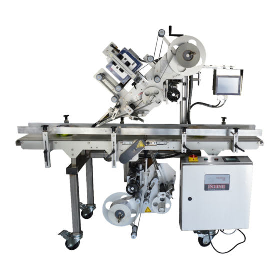
Page 4: Section One - General Information
SECTION ONE – GENERAL INFORMATION TERMINOLOGY OF A LABELING MACHINE 1. Dancer Arm 6. Pinch Roll 2. Label Height Adjustment 7. Take Up Reel 3. Coder Control Panel 8. Peel Plate 4. Linear Adjustment 9. Pinch Roll 5. Touchscreen 10. Coder... -
Page 5: Functional Description Of Machine
SPECIFICATIONS – STANDARD MACHINE ITEM SPECIFICATION LABEL HEIGHT 1 INCH TO 4.5 INCHES LABEL WIDTH (LENGTH) 1 INCH TO 14 INCHES LONG SPEED VARIABLE TO 1,000 IPM MAXIMUM RATE 100 LABELS/MINUTE LABEL GAP 1/8 INCH STANDARD (UP TO ¼ INCH ON SOME) CORE SIZE 3 INCHES IN DIAMETER ROLL SIZE... - Page 7 BASIC MACHINE CONTROLS MAIN INTERFACE MAIN POWER SWITCH CONVEYOR START CONVEYOR STOP...
- Page 8 SCREEN SETTINGS Main Screen 1. Batch count displays the current count of containers. Reset starts the count at 0. 2. Main Speed can be entered in inches/minute. 3. The buttons on the right take you to the screen named on the button. Label Settings (Top and Bottom Label identical) 1.
- Page 9 System Settings 1. Coder Dwell is the length of time the signal to fire the coder in 1/100 sec. 2. Date Coder can be turned on and off, which is the power for the Coder. 3. The Gap Error and Label Error can be bypassed of enable, and if enabled uses the times form the Timer page to produce the error.
-
Page 10: Section Two - Uncrating And Installation
SECTION TWO – UNCRATING AND INSTALLATION POWER AND AIR CONNECTIONS A grounded electrical male plug is provided with the machine, and is connected to the main electrical enclosure on the side of the machine. Plug this into any grounded receptacle. On machines with coders or that require air, an air filter/reservoir with a ¼”... -
Page 12: Section Three - Preparing For Operation
SECTION THREE – PREPARING FOR OPERATION SET CONVEYOR RAILS The conveyor guides must be set to the bottle diameter to ensure smooth control of the containers into and through the labeler. The right side of the labeler is fixed, that is, the side from which the label is applied is fixed to the conveyor. -
Page 13: Adjust Sensors
consistent labeling. The lower edge of the label web is 2 inches from the top of the Label Plate and so the lower Web Guides should be at that level. These can be measured with a ruler. The top Web Guides can then be moved up or down depending on the height of the label web being run. -
Page 14: Section Four - Operational Adjustments
SECTION FOUR – OPERATIONAL ADJUSTMENTS ADJUSTING LABEL TRACKING AND PRESENTATION TO PRODUCT The tracking of the label through the machine is extremely important to consistent labeling. If the label web “rides” up or down then the label will generally be skewed to one side or the other. The presentation of the label to the product is also paramount. -
Page 15: Section Five - Periodic Maintenance, Cleaning, And Lubrication
SECTION FIVE – PERIODIC MAINTENANCE, CLEANING, AND LUBRICATION MAINTENANCE There are very few maintenance items on the 700 Labeler. The three main factors to consider are: Clean the Drive Roll regularly. As the machine is used you will notice a film or line around the black Drive Roll. -
Page 16: Section Six - Troubleshooting
SECTION SIX – TROUBLESHOOTING NOTHING WORKS AT ALL 1. Check main power. Is machine plugged in? Is main power switch turned on? 2. Check fuses inside control panel. Bad fuses will be indicated by the red LED on the fuse holder. 3. - Page 17 LABELS ARE SKEWED ON CONTAINER Check the skew to see if it is all the same direction and about the same amount. If so, then check to see if the Peel Plate is square to the container. Use the turnbuckle to adjust the angle of attack of the label.
- Page 18 SECTION SEVEN – OPTIONS AND/OR SPECIAL COMPONENTS SUPPLIED WITH MACHINE (N/A)
- Page 19 SECTION EIGHT – PARTS LIST AND DIAGRAMS (SEE FOLLOWING PAGES)
Need help?
Do you have a question about the PARADIGM 700 and is the answer not in the manual?
Questions and answers