Table of Contents
Advertisement
Quick Links
D
ESIGN
Model GIR911
Infrared Carbon Dioxide
NOVA-Sensor
The information in this document is applicable to
sensors built on or after October, 2001
T h e i n f o r m a t i o n a n d t e c h n i c a l d a t a
d i s c l o s e d b y t h i s d o c u m e n t m a y b e
u s e d a n d d i s s e m i n a t e d o n l y f o r t h e
p u r p o s e s
a n d
s p e c i f i c a l l y
S
T
Y S T E M S
E C H N O L O G Y
i n f o r m a t i o n a n d t e c h n i c a l d a t a a r e
p r o p r i e t a r y
T
E C H N O L O G Y
d i s s e m i n a t e d e x c e p t a s p r o v i d e d i n t h e
f o r e g o i n g s e n t e n c e .
S
S
A F E T Y
2 3 2 8 2 M i l l C r e e k D r i v e , S u i t e 2 1 5
L a g u n a H i l l s , C a l i f o r n i a 9 2 6 5 3 ,
T e l ( 9 4 9 ) 5 8 3 - 1 8 5 7
w w w . s a f e t y s y s . c o m
M
ANUAL
7 0 0 7 1
t o
t h e
a u t h o r i z e d
b y
i n w r i t i n g . S u c h
t o
S
A F E T Y
a n d m a y n o t b e u s e d o r
Y S T E M S
F a x ( 9 0 9 ) 3 4 0 - 6 6 4 3
e x t e n t
S
A F E T Y
S
Y S T E M S
T
E C H N O L O G Y
U S A
Advertisement
Table of Contents

Summary of Contents for SAFETY SYSTEMS TECHNOLOGY GIR911
- Page 1 ESIGN ANUAL Model GIR911 Infrared Carbon Dioxide NOVA-Sensor 7 0 0 7 1 The information in this document is applicable to sensors built on or after October, 2001 T h e i n f o r m a t i o n a n d t e c h n i c a l d a t a...
-
Page 2: Table Of Contents
The GIR911 Unit ........ -
Page 3: Quick Start
MODEL GIR911 INFRARED CARBON DIOXIDE GAS NOVA-SENSOR MODEL GIR911 INFRARED CARBON DIOXIDE GAS NOVA-SENSOR QUICK START Apply Power Apply +24 volts DC to the labeled terminals (+24V, 24V RET). A 30 second countdown is displayed, followed by a brief display of the firmware revision (e.g. -
Page 4: Description
Principle of Operation The GIR911 uses the absorption of carbon dioxide at 4.25 µm for the detection of CO The GIR911 contains an incandescent lamp pulsed at 4 Hz in conjunction with two piezoelectric light sensors all contained in a plug-in housing ("optical bench"). In a patented configuration, the sensors are close to each other and are exposed to the direct light from the lamp, with no mirrors or other optical structures involved. -
Page 5: Technical Specifications
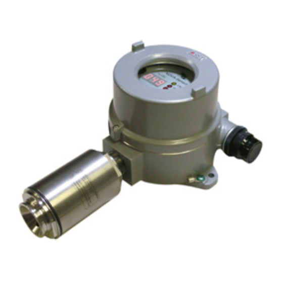
INSTALLATION The GIR911 Unit A complete GIR911 unit consists of an explosion-proof housing with MODE button, Infrared gas sensor head, terminal blocks for field wiring and transparent lid used to observe the operational status of the numerical readout and LED’s. The field wiring is connected to the terminal blocks inside the enclosure. -
Page 6: Mounting The Enclosure
• Calibration and functional check out with CompTest, if required Mounting the enclosure The dimensions of the GIR911 are shown in the figure below. It is preferable to attach the sensor to a wall or bracket, using bolts through the two mounting holes. However, these mountings may be omitted if the electrical conduit is sufficiently rigid to support the weight of the detector. -
Page 7: Wiring
MODEL GIR911 INFRARED CARBON DIOXIDE GAS NOVA-SENSOR Wiring Power input and Analog Signal Output A typical installation is shown in figure 911-2. This setup uses three wires between the NOVA-Sensor and the associated control modules. These wires carry the 24 VDC operating power for the sensor, and transmit the 20 mA signal to the controls. -
Page 8: Remote Sensor Version
The remote sensor version is the same as a standard version, except that the sensor head is located away from the electronics enclosure. A SST Model GIR910 Infrared carbon dioxide Gas Sensor is required for use with the remote GIR911 electronics package. A second 3/4 inch conduit connection is provided to connect the sensor electronics to the remotely located sensor head. -
Page 9: Dip Switch Settings
The GIR910 infrared gas sensor head is supplied with five color coded wires which connect to the terminals in the GIR911 electronics package. See figure 911-4 for hookup. Be extremely careful to connect each lead to the proper terminal. Interchanging two wires will almost always result in a burned out sensor. -
Page 10: Operation
MODEL GIR911 INFRARED CARBON DIOXIDE GAS NOVA-SENSOR alarm state until the NOVA-Sensor is manually reset with the MODE button or the remote reset signal. The DOWN position selects NON-LATCHING mode: after activation, the low alarm relay will return to the normal state as soon as the gas concentration sensed is less than the low alarm set point. -
Page 11: Calibration
Setpoints will “roll over” to zero at full scale Calibration The GIR911 NOVA-Sensor is pre-calibrated at the factory for the range by volume of CO as marked on the sensor head. It should be recalibrated in the field at regular intervals. - Page 12 MODEL GIR911 INFRARED CARBON DIOXIDE GAS NOVA-SENSOR In order to save gas it is recommended to apply calibration gas as soon as the 15-second count-down begins. Up to 3 minutes delay is tolerable for cases where the sensor head is at a remote location and the calibration gas must be applied through a long pipe.
-
Page 13: Balancing
3 1/2 minute time-out and thus abort the calibration procedure. Balancing “Balancing” the GIR911 Infrared Gas Sensor is performed by depressing the MODE button per the instructions above, but do not apply the calibration gas. This serves primarily to re-establish the zero reference of the detector. -
Page 14: Final Operational Check-Out (Comptest™)
MODEL GIR911 INFRARED CARBON DIOXIDE GAS NOVA-SENSOR Figure 911-5 Relay Contact Protection Scheme Relay Protection Circuitry Heavy duty relay contacts are provided in the NOVA-Sensor. These contacts are rated for resistive loads. If used for switching inductive loads, such as relay coils, lamps, beacons, etc., you must provide suitable suppression at the load. -
Page 15: How To Start The Comptest
MODEL GIR911 INFRARED CARBON DIOXIDE GAS NOVA-SENSOR to be entered within 6 minutes of applying power limits the CompTest to authorized personnel during system commissioning and periodic inspections. How to Start the CompTest WARNING: Do not execute the CompTest until verifying that all systems connected to the NOVA-Sensor are properly configured to execute a test. -
Page 16: Comptest™ Operational Sequence
CompTest security code. MAINTENANCE The GIR911 is easy to service. Most service activities will require the lid of the detector base or the enclosure of the GIR910 IR sensor head to be opened. CAUTION: Before opening lids or enclosures, the area must be free of... -
Page 17: Replacing The Sensor Lamp
Drifting/Shifting display Drifting or shifting or otherwise unexplainable display (i.e. display of negative or positive gas values with no apparent cause) on GIR911 Infrared NOVA-Sensors can have the following causes: 1) Bad contact between electronics module and terminal blocks in enclosure. This effect is noticeable when pressing on the installed electronics module from the top or when twisting it. -
Page 18: Wiring Of The Chassis Terminal
• the power supply used for the GIR911 must be floating with respect to EARTH/GND The reason for the change is that transient voltage suppressor diodes used in the GIR911 are internally connected to the CHASSIS terminal. This could cause problems in instal-...
Need help?
Do you have a question about the GIR911 and is the answer not in the manual?
Questions and answers