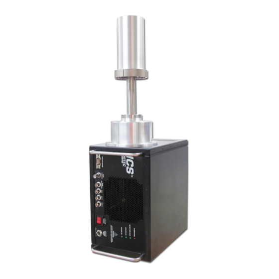
Summary of Contents for ORTEC ICS
- Page 1 ORTEC ® ™ Integrated Cryocooling System User Manual Printed in U.S.A. ORTEC® Part No. 806281 0415 Manual Revision B...
- Page 2 Copyright © 2015, Advanced Measurement Technology, Inc. All rights reserved. ORTEC® is a registered trademark of Advanced Measurement Technology, Inc. All other trademarks used herein are the property of their respective owners.
-
Page 3: Table Of Contents
OWER 4.2.1.3..........................5 NDICATORS 4.3. COOLING THE DETECTOR ..........................5 4.3.1. Changing the Orientation of the ICS During Operation ..............5 4.4. DETECTOR TESTING ............................5 4.5. DETECTOR PERFORMANCE MEASUREMENTS ....................5 INSTALLATION NOTES ..............................6 5.1. MOUNTING IN A SHIELD........................... 6 SPECIFICATIONS ................................ - Page 4 806281B / 0315 ADDITIONAL WARRANTY AND SAFETY NOTICES There are no serviceable parts in the ICS. Opening the enclosure or performing operations other than those described in this manual may void your warranty. Using this equipment in a manner not specified in this manual may impair the protection the equipment provides.
- Page 5 ® 806281B / 0315 ORTEC ICS™ Integrated Cryocooling System [Intentionally blank]...
- Page 6 ® ORTEC ICS™ Integrated Cryocooling System 806281B / 0315 PROPERTY OF AMETEK, INC. – ORTEC ®...
-
Page 7: Introduction
OPERATING CAUTIONS AND NOTES 3.1. HANDLING AND MOVING THE ICS WARNING Because of its weight, the ICS is rated by OSHA as a two-person lift. In addition, it is significantly nose-heavy. Keep this in mind when lifting and positioning the unit. -
Page 8: Electrical Cautions
DETECTOR WARMUP FOR REPOSITIONING OR SHIPPING Once the ICS is cooled, you can power off the ICS for a brief period (e.g., 10–20 minutes) without significantly warming the detector. When the cryocooler is restarted, the unit typically returns to ready status within a few minutes. The cryocooler can be restarted at any time without harming the detector element, regardless of whether the detector is warm, partially cooled, or cooled to operating temperature. -
Page 9: System Overview
ICS™ Integrated Cryocooling System SYSTEM OVERVIEW 4.1. CONTENTS OF THE SHIPPING CARTON When you receive the ICS, its shipping carton(s) will contain the following components at minimum: ICS integrated detector/cryocooler. Region-specific ac/dc power adapter and cord. Detector cable kit. This ICS user manual; the Photon Detector Manual containing performance and testing information for your detector type;... -
Page 10: Connectors And Indicators
HV SHV connector connects to detector bias (high-voltage) input on MCB or NIM amplifier. SHUTDOWN BNC turns off the bias supply voltage when the detector is warm. Software-selectable ORTEC or TTL mode (SMART-1® detectors auto-select the SMART shutdown mode). In ORTEC mode, the detector’s Bias Shutdown cable must be connected to this input or the high voltage will not turn on. -
Page 11: Indicators
4.3.1. Changing the Orientation of the ICS During Operation Before changing the orientation of the ICS, switch power OFF then restore power when the unit is in it new position. 4.4. DETECTOR TESTING See the accompanying Photon Detector Manual, which contains testing information specific to the detector mounted on your ICS. -
Page 12: Installation Notes
806281B / 0315 INSTALLATION NOTES The ICS can be mounted on a stand (with or without a lead shield) or on the ISO-CART II, or can be placed on a benchtop. The two vented panels must have at least 13 mm (0.5 in.) of ventilation space. You may remove the rubber feet, if you wish. -
Page 13: Electrical And Mechanical
Environmental Temperature range: −5°C to +40°C. Humidity: non-condensing. Maximum Storage Temperature +50°C. Electrical Supply 100–240 V ac (50/60 Hz) auto ranging. UPS/Battery Backup ICS is compatible with commercial batteries and universal power supplies (UPS). ORTEC offers an optional UPS. Power Usage 70 W typical, 130 W maximum. -
Page 14: Dimensions
Choose from 051, 064, 076, 089, 102, 114, 127, 140, 152, 165, ICS-LL 178, 191, 203, 216, 229, 241, 254, 267, 279, 292, or 305 [Note: 102 mm (4 in.) is typical length.] PROPERTY OF AMETEK, INC. – ORTEC ®...

Need help?
Do you have a question about the ICS and is the answer not in the manual?
Questions and answers