Table of Contents
Advertisement
Quick Links
Advertisement
Table of Contents

Summary of Contents for SystemBase eCAN
- Page 1 User Manual www.sysbas.com Version 1.0 2021/07/02...
- Page 2 Revision History Document Pages Revision Date Revised/Added/Removed Details of Revision Ver. Revised 2021.07.02...
-
Page 3: Table Of Contents
7. SETTING EXAMPLES ....................21 --------------------------------------------------------------------------------------------------------------- 1. SPECIFICATION ......................23 2. DIMENSION ........................25 3. CAN PORT PIN SPECIFICATION .................. 26 4. SETTING MENU......................27 5. ECAN FRAME STRUCTURE ..................30 6. ECANVIEW ........................35 7. CERTIFICATION ......................40 8. COPYRIGHT ........................40... -
Page 4: Can
User Manual Please be sure to read this manual before using and use the product safely and accurately. • Pictures and photos in the manual may be different from the physical, and the document is subject to change without notice to improve performance. For the last information, please visit our website (www.sysbas.com). - Page 5 User Manual 1. CAN CAN was developed to cause this problem by German company Bosch in 1986. It used bus communication method rather than 1:1 communication method which UART based serial communication has, and various technologies were incorporated to prevent communication conflicts.
-
Page 6: Components
User Manual 2. Components Components Ordering Information eCAN, 5V DC Adaptor, LAN Cable, eCAN Warranty/Download Guide... -
Page 7: Product
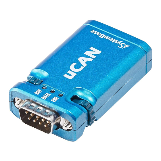
User Manual 3. Product Connector DC Adaptor, LAN Port CAN Port(Male) State Operation RDY(Ready) Blink Blinks when power is applied and boots normally DATA(Data) Blink LED blinks when sending/receiving data LNK(Link) On/Off/ Lights when Ethernet socket is connected Blink... - Page 8 User Manual Button Press RST button less than 3 seconds: Reset equipment Press RST button more than 3 seconds: Factory initialize equipment (Please refer to the APPENDIX for initialization values) Switch Switch Number Status Operation Switch1, 4 Not used Enable termination resistance of 120Ω...
-
Page 9: Features
2) CAN VBUS Power Supply Feature In addition to the 5V Power supply through DC adapter, eCAN can be also powered by pin no.9 of the CAN port. 3) VCP(Virtual Com Port) Function ComRedirector, a virtual COM Port(VCP) among the utilities provided, enables using LAN port of the eCAN connected to the same network as if it were a serial port mounted on a PC. -
Page 10: How To Use
5. How to Use Connection between CAN equipment(CAN Bus) and PC eCAN performs ComRedirector, TCP Server/Client and UPD connection over the network. Users can check CAN data on PC over the network, or generate CAN data and forward it to CAN Bus. -
Page 11: How To Setup
Setting through Web Page (1) Preparation for Connection(when connecting PC-eCAN without AP) To connect eCAN and PC directly, you need to set the network address of the PC environment. Please follow the order of setup as bellow. 1. Go to Control Panel\Network and Internet\Network Connection and open the Ethernet icon. - Page 12 User Manual 3. Click Internet protocol version(TCP/IPv4) and then click Properties.
- Page 13 User Manual 4. Click “Use IP Address(S)” and enter IP address. 5. Enter the IP address and subnet mask address and click “OK”.
- Page 14 User Manual (2) Web Connection Open a web browser and enter the IP address of the eCAN. Then the authentication window appears on the first connection. Default ID is “ecan”, password is “99999999(eight nines)”. After login, the web settings page appears.
- Page 15 User Manual Precautions for Accessing the Web The setting using the web is not supported in the network environment below 10Mbps. eCAN 10Mbps Therefore, if you change the settings using the web, you should connect the integrated device to the 100Mbps network environment or PC as below.
- Page 16 User Manual (3) Network Setting The network Setting pages appears on the initial screen of the Web Settings page, that shows network information for the equipment. The screen on the page is as follows. You can set your network environment and management in the Network Setting. After changing the settings, you must press the [Submit] button to save the changed value and restart it through the Reboot menu to apply it to the actual equipment operation.
- Page 17 User Manual (4) CAN Setting You can set the operating environment for CAN port in CAN Settings. After changing the settings, you must press the [Submit] button to save the changed value and restart it through the Reboot menu to apply it to the actual equipment operation. If you exit without saving the changes, the changed value will be lost.
- Page 18 User Manual (5) Filter Setting You can set the SW Filter for the eCAN. SW Filter is a feature that blocks a single ID unlike ID and MASK, and can set up to 32 SW Filter. If you specify the ID and properties to filter, only those IDs will not be received.
- Page 19 ID and password, you can reset it to the default ID and password by pressing the RST button for more than 3 seconds. (7) Reboot The device will be restarted. If you have changed the setting and save it via [Submit], you must press the [Reboot] button to restart the eCAN to reflect the set values normally.
- Page 20 1: You can set Network, Operation Mode, CAN Setting, Filter Setting. 2: Click Export button to save the information currently set in the eCAN to your PC. 3: Click Apply button to save and apply the changed setup information to the device.
- Page 21 User Manual (4) Upgrade Firmware You can upgrade the firmware for the selected device. (5) Apply You can set the Device Name, IP Address, Subnet Mask, and Gateway in the searched Device List. If you click [Apply] after changing, it applies to each device that has changed its settings. However, if the network information changes,...
-
Page 22: Setting Examples
User Manual 7. Setting Examples Based on the information above, this chapter explains easy setup information through various connections. You can understand how to set the following configuration as an example. Connection between CAN equipment(CAN Bus) and PC PC Connected LAN... - Page 23 User Manual Connection between CAN equipment(CAN Buses) To enable communication between different CAN Buses, set two eCANs to Server and Client(Target: Server) and connect to AP. Category eCAN PC Connected AP Connection Type: Static Connection Type: Static Device IP Address: 192.168.0.100 Device IP Address: 192.168.0.200...
-
Page 24: Specification
-40 ~ 85℃ (-40 ~ 185℉) Humidity Max. 90% R.H RDY(Yellow), DATA(Red), LINK(Green) Protection ± 15kV ESD Protection Reset Button Feature Warm Booting Factory Default Operation Press less than 3 sec Press more than 3 sec Result eCAN restart eCAN factory initialization... - Page 25 User Manual Software Protocol TCP, UDP, ICMP, DHCP, HTTP Operation Mode COM Redirector, TCP Server/Client, UDP Server/Client Utility COM Redirector Configuration Web, eCANConfig...
-
Page 26: Dimension
User Manual 2. Dimension... -
Page 27: Can Port Pin Specification
User Manual 3. CAN Port Pin Specification CAN DB9 Male Pin No. Signal Description CAN_L CAN Low Signal Ground CAN_H CAN High Signal 5VDC Power... -
Page 28: Setting Menu
User Manual 4. Setting Menu The main menus of Network Setup are as follows: Menu Default Description Device Name eCAN Set the name of the device. MAC Address Own Address Displays own MAC Address. Select the IP type to set for the device. - Page 29 TCP Client When a particular server on the network waits for a connection, eCAN acts as a client of socket and attempts to connect with the IP address and socket number of the Server which is set. Data Operation Mode...
- Page 30 User Manual Decide whether to collect and process data sent and received over Ethernet during TCP communication. When set to Disable, TCP transmission and reception data are collected. So there is a delay between Ethernet transmission and CAN transmission. But it is advantageous for high speed data and...
-
Page 31: Ecan Frame Structure
The total length of the eCAN Data Frame is 14bytes and consists of TYPE · ID · DLC · DATA. eCAN Error Frame The total length of the eCAN Error Frame is 14bytes and consists of TYPE · Status · REC · TEC · LEC. When Request, it request 14bytes including Type(0xFF). - Page 32 Send Receive - 04 00 00 01 23 06 31 32 33 34 35 36 00 00 (hex) eCAN Error Frame Structure Status represents the current state and its values are described in the table below. Set Type to 1byte, the minimum value.
- Page 33 Error Frame 0x21 (!) eCAN Data Frame The total length of the eCAN Error Frame is 9bytes and consists of TYPE(1) · Status(1) · REC(2) · TEC(2) · LEC(2) · CR(1). When Request, it request ‘!’(0x21) 1byte. Ex) 0x21 (! ASCII)
- Page 34 User Manual eCAN Data Frame Structure The total length of the eCAN Data Frame is 6~22bytes and consists of TYPE · ID · DLC · DATA · CR(0x0D. eCAN Error Frame Set TYPE to 1byte. Set ID to STD Frame value(3byte, ASCII) or to EXT Frame value(8byte, ASCII).
- Page 35 User Manual 0x31~0x36 Error Passive 0x37 Bus off State REC (Rx Error Counter) It is the reception error counter. It consists of 2bytes, which are delivered by converting values from 0~255 to hex, and each hex value to ASCII.
-
Page 36: Ecanview
DLC: Specifies the Data length of CAN Frame Data: Specifies the CAN Frame Data to Hex value. TX Count: Counts CAN frames sent from eCANView to eCAN. RX Count: Counts CAN frames sent from eCAN to eCANView.. Interval: Sets the auto transmission mode and period. - Page 37 User Manual Action You can select either the Connect menu or the Disconnect menu. Connect Depending on the operating mode of the eCAN, you can specify a VCP, TCP Server/Client, UDP connection.
- Page 38 User Manual Example of Use 1. Connect two eCANViews to the network and set them up as below. eCAN1 = TCP Server - 192:168:0;225:4001, 250kbps, set Spec B and reboot eCAN2 = TCP Server - 192:168:0;226:4001, 250kbps, set Spec B and reboot 2.
- Page 39 User Manual 7. To connect eCAN2, perform steps 3~6 again with the address of eCAN2. 8. Configure the CAN Frame in the eCANView connected with eCAN1 and press the [Send] button.
- Page 40 You can save communication data on the screen through [Log Save] in the menu. *If communication between eCANs is not carried out normally, please check the eCAN settings, or set the termination resistance by switching switch no.2 and 3 on the back of the product to ON.
-
Page 41: Certification
EN 61000-3-2:2014 EN 61000-3-3:2013 8. Copyright Copyright ⓒ 2021 SystemBase Co., Ltd. All rights reserved. This manual is a document protected by Copyright law. Unauthorized copying, duplicating, publishing of some or all of contents without prior consent from SystemBase is against Copyright Law. - Page 42 If you have any inconvenience while using the product, please contact us. Email: Working Hour • Purchase/Quotation: overseas@sysbas.com • Technical Support/RMA: tech@sysbas.com MON ~ FRI 9:00 ~ 18:00 www.sysbas.com Tel: +82-2-855-0501 Fax: +82-2-855-0580...
Need help?
Do you have a question about the eCAN and is the answer not in the manual?
Questions and answers