Table of Contents
Advertisement
Quick Links
Advertisement
Table of Contents

Summary of Contents for ONOSOKKI DS-5000 Series
- Page 1 DS- 5000 Series Data Station Instruction Manual -Speci cations-...
- Page 2 3-9-3 Shin-Yokohama, Kohoku-ku, Yokohama 222-8507, Japan Phone : +81-45-476-9725 / Fax : +81-45-476-9726 (Overseas sales section) E-mail : overseas@onosokki.co.jp ■ WARRANTY ■ 1. This product is covered by a warranty for a period of one year from the date of purchase.
- Page 3 This manual ( DS-5000 Series Instruction Manual - Specifications -) describes the handling methods, precautions, parts names and functions, specifications, etc. for the DS-5000 series Data Station. Be sure to read warnings and cautions provided in this manual before use in order to use the DS-5000 series Data Station safely and correctly.
- Page 4 ・Use the DS-5000 series Data Station by following the instructions described in this manual. ・The precautions specific to the DS-5000 series Data Station may be noted on the main unit or in other instruction manuals accompanying it. These precautions must also be observed when you use the product.
- Page 5 Be sure to understand warnings and cautions provided in this chapter before use in order to use the DS-5000 series Data Station safely and correctly. ● General Precautions WARNING ・Do not use this product for the operations involving human lives or requiring a high level of reliability.
- Page 6 ・Do not install the product in an unspecified place. Do not put the DS-5000 series Data Station in the following places or the places not specified in this manual. There is a risk of fire or injury. Dusty place/ damp place such as near a water...
- Page 7 DS-5000 series Data Station, but also risk of electric shock or fire. ・Do not handle the devices with the plug inserted. Before performing maintenance of the devices, turn off the power of the DS-5000 series Data Station and then disconnect the power plug. Even when the power is turned off, there is a risk of electric shock if you touch an internal part of the product with the power cable connected.
- Page 8 ・If the power supply is stopped due to power failure or other reasons while the system is used with the AC adapter ( without the DS-0501 Battery Unit For DS-5000 series) , the power supply to the main unit is interrupted instantaneously.
- Page 9 Power cable for AC adapter ( 3) Instruction manual This manual Connects the DS-5000 series Data Station with ( 4) LAN cable ( 3 m) a personal computer. ・If any of the items are missing or damaged, contact your nearest Ono Sokki sales office or the CAUTION distributor where you purchased the product immediately.
- Page 10 viii...
-
Page 11: Table Of Contents
㌀ ㌀ ㌀ ㌀ ㌀ ㌀ ㌀ ㌀ ㌀ ㌀ ㌀ ㌀ ㌀ ㌀ ㌀ ㌀ ㌀ ㌀ ㌀ ㌀ ㌀ ㌀ ㌀ ㌀ ㌀ ㌀ ㌀ ㌀ ㌀ ㌀ ㌀ ㌀ ㌀ ㌀ ㌀ ㌀ ㌀ ㌀ ㌀ ㌀ ㌀ ㌀ ㌀ ㌀ ㌀ ㌀ ㌀ ㌀ ㌀ ㌀ ㌀ ㌀ ㌀ ㌀ ㌀ ㌀ ㌀ ㌀ ㌀ ㌀ ㌀ ㌀ ㌀ 3. 1 Precautions for DS-0501 Battery Unit For DS-5000 series ㌀... - Page 12 DS-0523/ 0526/ 0532/ 0534 Input Unit ㌀ ㌀ ㌀ ㌀ ㌀ ㌀ ㌀ ㌀ ㌀ ㌀ ㌀ ㌀ ㌀ ㌀ ㌀ ㌀ ㌀ ㌀ ㌀ ㌀ ㌀ ㌀ ㌀ ㌀ ㌀ ㌀ ㌀ ㌀ ㌀ ㌀ ㌀ ㌀ ㌀ ㌀ ㌀ ㌀ ㌀ ㌀ ㌀ ㌀ ㌀ ㌀ ㌀ ㌀ ㌀ ㌀ ㌀ ㌀ ㌀ ㌀ ㌀ ㌀ ㌀ ㌀ ㌀ ㌀ ㌀ ㌀ ㌀ ㌀ ㌀ ㌀ ㌀ ㌀ ㌀ ㌀ ㌀ ㌀ ㌀ ㌀ ㌀ ㌀ ㌀ ㌀ 4.
- Page 13 7. 3 Hardware-to-Hardware Connection Method ㌀ ㌀ ㌀ ㌀ ㌀ ㌀ ㌀ ㌀ ㌀ ㌀ ㌀ ㌀ ㌀ ㌀ ㌀ ㌀ ㌀ ㌀ ㌀ ㌀ ㌀ ㌀ ㌀ ㌀ ㌀ ㌀ ㌀ ㌀ ㌀ ㌀ ㌀ ㌀ ㌀ ㌀ ㌀ ㌀ ㌀ ㌀ ㌀ ㌀ ㌀ ㌀ ㌀ ㌀ ㌀ ㌀ ㌀ ㌀ ㌀ ㌀ ㌀ ㌀ ㌀ ㌀ ㌀ ㌀ ㌀ ㌀ ㌀ ㌀ ㌀ ㌀ ㌀ ㌀ ㌀ ㌀ 7.
- Page 14 Table of Contents...
-
Page 15: Overview Of Ds-5000
Overview of DS-5000 Overview of DS-5000 1. 1 Overview of DS-5000 1. 1. 1 Operation Environment ■ Specifications ● Common Specifications Interface LAN terminal 1000base-T Microsoft® Windows® 10 Pro Microsoft® Windows® 10 Enterprise Microsoft® Windows® 10 Education ( 64-bit) ・Use the personal computer with Version 2004 or later, and OS Build 19041. 508 or later. ・Required to install . - Page 16 When you plan to purchase a personal computer to be connected with the DS-5000 series, we recommend that you contact your nearest Ono Sokki sales office or the distributor where you purchased the product.
- Page 17 Overview of DS-5000 ● HDD ( Built-in Type) To use the built-in type HDD, the external hard disk case is required. It is recommend to use the External Hard Disk Case LGB-EKU3 ( 3. 5 inches) manufactured by Logitec which has been checked by Ono Sokki for operations. When using the built-in type HDD, install the HDD to LGB-EKU3 ( 3.
-
Page 18: Ds-5000 Unit Configuration
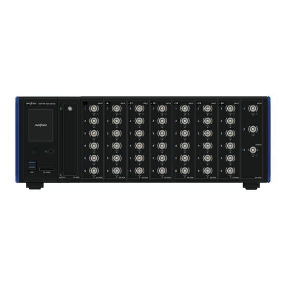
1. 1. 2 DS-5000 Unit Configuration The DS-5000 series Data Station is a multi-unit measurement system with the configuration suitable for the intended use and purpose by adding the required number of individual units such as input, signal output, and battery units to the DS-5100 Main Unit which works as the base system as shown below. - Page 19 References DS-5100 Main Unit DS-5100 Main Unit DS-0501 Battery Unit For DS-5000 series DS-0501 Battery Unit For DS-5000 series DS-0523 3ch 40kHz Input Unit DS-0523/ 0526/ 0532/ 0534 Input Unit DS-0526 6ch 40kHz Input Unit DS-0523/ 0526/ 0532/ 0534 Input Unit...
-
Page 20: Example Of Peripheral Device Connection To Ds-5000
Overview of DS-5000 1. 1. 3 Example of Peripheral Device Connection to DS-5000 ・For details about the devices that can be connected to the DS-5000 series Data Station, contact CAUTION your nearest Ono Sokki sales office or the distributor where you purchased the system. - Page 21 Overview of DS-5000 ■ Connecting Peripheral Devices to DS-0542 External Input Unit/ DS-0545 Signal Output Unit DS-5100 Data Station 42 Vpk 42 Vpk 42 Vpk 42 Vpk 42 Vpk 42 Vpk 42 Vpk SD CARD BATTERY 1. 1 Overview of DS-5000...
-
Page 22: Ds-5000 Outside Dimensions
Overview of DS-5000 1. 2 DS-5000 Outside Dimensions... -
Page 23: Ds-5100 Main Unit
・If the power supply is stopped due to power failure or other reasons while the system is used with the AC adapter ( without the DS-0501 Battery Unit For DS-5000 series) , the power supply to the main unit is interrupted instantaneously. - Page 24 DS-5100 Main Unit CAUTION ・Insert only an SD card to the SD card slot. Inserting any other object may cause failure. If ingress of foreign object or water occurs, remove the power supply such as AC adapter immediately and then contact your nearest Ono Sokki sales office or the distributor where you purchased the system.
-
Page 25: Overview Of Ds-5100 Main Unit
・Power to the DS-5100 Main Unit is supplied from the supplied AC adapter ( regardless of the unit configuration) . ・Operation by battery is available by adding the optional DS-0501 Battery Unit For DS-5000 series. ・Up to five DS-5100 units can be operated in an interlocking manner using the hardware connection cables between them. - Page 26 DS-5100 Main Unit Windows© Embedded ONO SOKKI MADE IN JAPAN LAN (RJ45) connector (IN) A terminal used to connect a personal computer and the DS-5100 Main Unit. When two or more units of the DS-5100 Main Unit are connected (hardware-to-hardware connection), this terminal is connected to LAN (OUT) of another DS-5100.
-
Page 27: Ds-5100 Main Unit Specifications
DS-5100 Main Unit 2. 3 DS-5100 Main Unit Specifications ● System Configuration 40-kHz system 100-kHz system Maximum number of input channels 48 ch 4 ch Maximum number of output channels 6 ch 2 ch Maximum number of external input 4 ch 4 ch channels ( revolution/ trigger) Maximum number of summation... - Page 28 DS-5100 Main Unit Maximum hardware-to-hardware Maximum 5 units None connection ● Number of channels available when Hardware to Hardware connection used Maximum number of input chan- 240 ch nels ・48 ch x 5 units Maximum number of output 6 ch channels ・Output is available only for the hardware connected to a PC.
- Page 29 DS-5100 Main Unit ● DS-5100 General Specifications Outside dimensions 60 mm ( W) x 160 mm ( H) x 221 mm ( D) , protrusions not included Power supply voltage 19 VDC Power supply connector 5. 5 mm x 2. 5 mm Power consumption Maximum 13 W Operating temperature range...
-
Page 30: Ds-0501 Battery Unit For Ds-5000 Series
DS-0501 Battery Unit For DS-5000 series DS-0501 Battery Unit For DS-5000 series 3. 1 Precautions for DS-0501 Battery Unit For DS-5000 series WARNING ・Do not use an unspecified AC adapter. Do not use an unspecified AC adapter which is not supplied with the product. There is a risk of electric shock or fire. - Page 31 ・If the DS-5000 series Data Station is not used for a long time, remove the lithium-ion battery from the main unit and then store it.
-
Page 32: Overview Of Ds-0501 Battery Unit For Ds-5000 Series
3. 2 Overview of DS-0501 Battery Unit For DS-5000 series 3. 2. 1 Overview of Battery Unit The DS-0501 Battery Unit For DS-5000 series is an optional power supply unit that supplies power to the DS-5100 Main Unit by the built-in lithium-ion battery. -
Page 33: Parts Names And Functions Of Battery Unit
DC INPUT (external DC power input connector) A connector for external DC power input (10 to 28 VDC). * The battery is not charged by the external DC power input. 3. 2 Overview of DS-0501 Battery Unit For DS-5000 series... -
Page 34: Precautions For Handling Battery Unit
■ Precautions for Charging in Multi-channel Configuration ・When performing charging with the power of the DS-5000 series Data Station main unit turned on, the operation of the DS-5000 series Data Station main unit is given priority. Therefore, in the multi-channel configuration where multiple input units are connected, the charging time may become longer or charging may not be performed. -
Page 35: Lithium-Ion Battery Mounting Procedure
■ Precautions for DC INPUT With the power of the DS-5000 series Data Station main unit turned on, do not make a switch between the AC adapter and the external DC power input without mounting the battery pack. The power may be turned off automatically. - Page 36 DS-0501 Battery Unit For DS-5000 series Screw fixing the battery slot cover Battery pack Battery slot cover ● Checking Battery Pack Charge Level The battery pack is equipped with indicator lamps and switch to display the charge level. When the charge level confirmation switch is pressed, the indicator lamp turns on to display the charge level.
-
Page 37: Ds-0501 Battery Unit For Ds-5000 Series Specifications
DS-0501 Battery Unit For DS-5000 series 3. 3 DS-0501 Battery Unit For DS-5000 series Specifications ● DS-0501 General Specifications Outside dimensions 40 mm ( W) x 160 mm ( H) x 221 mm ( D) , protrusions not included External DC power input voltage 10 to 28 VDC ( battery unit required)... -
Page 38: Ds-0523/ 0526/ 0532/ 0534 Input Unit
DS-0523/ 0526/ 0532/ 0534 Input Unit DS-0523/ 0526/ 0532/ 0534 Input Unit 4. 1 Precautions for Input Unit WARNING ・Do not apply an input voltage exceeding the rating to the BNC connector. Applying an input voltage exceeding the rating may cause failure of the input unit, electric shock or damage. -
Page 39: Overview Of Input Unit
DS-0523/ 0526/ 0532/ 0534 Input Unit 4. 2 Overview of Input Unit 4. 2. 1 Overview of Input Unit DS-0523 3ch 40kHz Input Unit and DS-0526 6ch 40kHz Input Unit have a frequency band of 40 kHz. DS-0532 2ch 100kHz Input Unit and DS-0534 4ch 100kHz Input Unit have a frequency band of 100 kHz. The input units are used to analyze the time axis and frequency axis of general signals. -
Page 40: Parts Names And Functions Of Ds-0532/ 0534 100Khz Input Unit
DS-0523/ 0526/ 0532/ 0534 Input Unit 4. 2. 3 Parts Names and Functions of DS-0532/ 0534 100kHz Input Unit 42 Vpk 42 Vpk Status LED Green light turns on: The specified channel is turned on in green by the application function. Red light turns on/blinks: Input of a signal exceeding the set voltage range causes the light to turn on or blink in red. -
Page 41: Input Unit Specifications
DS-0523/ 0526/ 0532/ 0534 Input Unit 4. 3 Input Unit Specifications 4. 3. 1 DS-0523/ 0526 40kHz Input Unit Specifications DS-0523 3 ch Number of input channels DS-0526 6 ch Input terminal shape Input impedance 1 MΩ ±0. 5 % 100 pF or less Single end Input format ・Each channel isolated ( always) - Page 42 DS-0523/ 0526/ 0532/ 0534 Input Unit Less than 20 kHz ±0. 1 dB Channel-to-channel gain accu- racy ( within the same range) 20 kHz or more ±0. 2 dB Less than 20 kHz ±0. 1 ° Channel-to-channel phase ac- curacy ( within the single unit) 20 kHz or more ±0.
-
Page 43: Ds-0532/ 0534 100Khz Input Unit Specifications
DS-0523/ 0526/ 0532/ 0534 Input Unit 4. 3. 2 DS-0532/ 0534 100kHz Input Unit Specifications DS-0532 2 ch Number of input channels DS-0534 4 ch Input terminal shape Input impedance 1 MΩ ±0. 5 % 100 pF or less Single end Input format ・Each channel isolated ( always) 42. - Page 44 DS-0523/ 0526/ 0532/ 0534 Input Unit Less than 20 kHz ±0. 1 ° Channel-to-channel phase ac- curacy 20 kHz or more ±0. 7 ° 3rd order Anti-aliasing filter LPF 300 kHz, -3 dB Butterworth ● DS-0532/ 0534 100-kHz Input Unit General Specifications Outside dimensions 40 mm ( W) x 160 mm ( H) x 221 mm ( D) , protrusions not included Power supply...
-
Page 45: Ds-0542/ 0543/ 0544 External Input Unit
DS-0542/ 0543/ 0544 External Input Unit DS-0542/ 0543/ 0544 External Input Unit 5. 1 Precautions for External Input Unit WARNING ・Do not apply an input voltage exceeding the rating to the BNC connector. Applying an input voltage exceeding the rating may cause failure of the external input unit, electric shock or damage. -
Page 46: Overview Of External Input Unit
DS-0542/ 0543/ 0544 External Input Unit 5. 2 Overview of External Input Unit 5. 2. 1 Overview of External Input Unit The DS-0542 2ch External Input Unit, DS-0544 4ch External Input Unit, and DS-0543 2ch External Input & 1ch Signal Output Unit are used to input external trigger signals or revolution pulse signals from a handheld tachometer or digital tachometer. - Page 47 DS-0542/ 0543/ 0544 External Input Unit 5. 2. 3 Parts Names and Functions of DS-0543 2ch External Input & 1ch Signal Output Unit Input BNC connector Terminals used to input external timing signals or revolution pulse signals. 42 Vpk Status LED Green light turns on/blinks: Detection of input signal causes the light to turn on or blink in green.
-
Page 48: External Input Unit Specifications
DS-0542/ 0543/ 0544 External Input Unit 5. 3 External Input Unit Specifications 5. 3. 1 DS-0542 2ch/ 0544 4ch External Input Unit Specifications DS-0542 Input: 2 ch Number of channels DS-0544 Input: 4 ch Input terminal shape Input impedance 100 kΩ ±0. 5 % Single end Input format ・Each channel isolated ( always) -
Page 49: Ds-0543 2Ch External Input & 1Ch Signal Output Unit
DS-0542/ 0543/ 0544 External Input Unit 5. 3. 2 DS-0543 2ch External Input & 1ch Signal Output Unit ● DS-0543 Input Specifications Number of input channels 2 ch Input terminal shape Input impedance 100 kΩ ±0. 5 % Single end Input format ・Each channel isolated ( always) 42. - Page 50 DS-0542/ 0543/ 0544 External Input Unit D/ A converter 24 bit ΔΣ type Sine wave, swept sine, random ( no inter-channel correlation) , pseudo Signal type random, impulse, octave band noise, pink noise, record data THD and spurious -75 dB or less ( sine wave 1 kHz, amplitude ±1 V output) Applicable FFT analysis length 64 to 16384 ( power of 2) Zoom analysis...
-
Page 51: Ds-0545 2Ch Signal Output Unit
DS-0545 2ch Signal Output Unit DS-0545 2ch Signal Output Unit 6. 1 Precautions for Signal Output Unit WARNING ・Do not input an external signal to the output channel of the DS-0545 2ch Signal Output Unit. Inputting an external signal to the output channel may cause failure of the DS-0545 2ch Signal Output Unit, electric shock or damage. -
Page 52: Overview Of Signal Output Unit
DS-0545 2ch Signal Output Unit 6. 2 Overview of Signal Output Unit 6. 2. 1 Overview of DS-0545 2ch Signal Output Unit The DS-0545 2ch Signal Output Unit outputs various signal waveforms ( sine wave/ swept sine/ random, etc. ) . The output isolated electrically is suitable for servo analysis, etc. -
Page 53: Signal Output Unit Specifications
DS-0545 2ch Signal Output Unit 6. 3 Signal Output Unit Specifications 6. 3. 1 Output Specifications Number of output channels 2 ch Output terminal shape Output impedance 0 Ω or 50 Ω ±10 % 42. 4 Vpk ・Between BNC ground and frame ground, and between each BNC ground Isolation ・Output connector CH2 and summation input connector within the unit are isolated collectively. -
Page 54: Summation Function Specifications
DS-0545 2ch Signal Output Unit 6. 3. 2 Summation Function Specifications Input terminal shape Input range ±10 V ( sum of voltage amplitude, summation signal and offset: within ±10 V) Input impedance 1 MΩ ±0. 5 % ( 100 pF or less) Input format Single end Input coupling... -
Page 55: Hardware-To-Hardware Connection Function
DS-5100 Main Unit, which may result in failure. Before using, be sure to check that the grounding terminals of the outlets have the same potential. ・Do not touch the DS-5000 series Data Station main unit or cables with wet hands. There is a risk of electric shock. -
Page 56: Overview Of Hardware-To-Hardware Connection Function
LAN cables for communication. Up to five units of DS-5000 series Data Station can be connected. For example, you can connect two units of DS-5000 having six channels and use as a system having 12 channels temporarily. - Page 57 Hardware-to-Hardware Connection Function ・Insert the cable surely and then fix it using cable retaining screws to prevent coming off. CAUTION ・Be sure to tighten the cable retaining screws at a tightening torque of 0. 1 N・m or less. ■ LAN Cable Connect the LAN IN and LAN OUT terminals using the LAN cable ( 3/ 10 m) for communication specified by Ono Sokki.
- Page 58 ① Turn on the power of each unit of the DS-5000 series Data Station ( in any oder) . ② After checking that all the units of DS-5000 series Data Station forming hardware-to-hardware connection are...
- Page 59 ・ Assignment of channels is determined in the connection order of hardware connection cable for synchronization. The DS-5000 series Data Station with the hardware connection cable connected to only the SYNC OUT side becomes the first unit. For the subsequent hardware, channel numbers are assigned automatically by the O-Solution in the connection order of hardware connection cable.
- Page 60 Hardware-to-Hardware Connection Function ・When the O-Solution is started in the middle of the startup process of the DS-5000 series Data CAUTION Station, connection cannot be performed correctly. Be sure to check that the information is displayed ( completion of startup) on the LCD of DS-5000 series Data Station main unit before starting the O-Solution.
- Page 62 900000581 / IM20082502(1.2)
Need help?
Do you have a question about the DS-5000 Series and is the answer not in the manual?
Questions and answers