Table of Contents
Advertisement
Quick Links
Advertisement
Table of Contents

Related Manuals for Matsushita Electric KX-T2378JXW


Summary of Contents for Matsushita Electric KX-T2378JXW
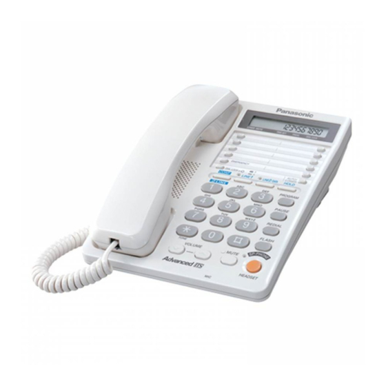
- Page 1 ORDER NO. KM40112760C3 Telephone Equipment KX-T2378JXW Intergrated Telephone System White Version (for Asia, Middle Near East and Other Areas) SPECIFICATIONS 2002 Kyushu Matsushita Electric Co., Ltd. All rights reserved. Unauthorized copying and distribution is a violation of law.
-
Page 2: Location Of Controls
1. LOCATION OF CONTROLS... - Page 4 2. DISPLAY...
-
Page 5: Connecting The Handset
3. CONNECTION 3.1. Connecting the Handset Connect the handset as shown below. -
Page 6: Connecting The Telephone Line Cord
- Use only a Panasonic Handset for the KX-T2378JXW. 3.2. Connecting the Telephone Line Cord Connect the telephone line cord(s) to the unit as follows. To connect a two-line telephone jack To connect two single-line telephone jacks... -
Page 7: Connecting A Communication Device
If you use the unit only as a single-line telephone 3.3. Connecting a Communication Device After connecting the telephone line cord to a two-line telephone jack, you can connect a communication device (computer, modem, fax, answering machine, etc.) through this unit using the LINE2/DATA jack. -
Page 8: Selecting The Dialing Mode
- If the LINE2/DATA indicator lights red, the communication device is in use. Use LINE1 to make or answer other calls. Otherwise the communication device may not operate properly. 4. SETTINGS 4.1. Selecting the Dialing Mode You can select the dialing mode by programming. If you have touch tone service, set to "Tone". If rotary or pulse service is used, set to "Pulse". -
Page 9: Time Adjustment
4.2. Time Adjustment You can select AM/PM or 24-hour clock by programming. Make sure that a call is not put on hold. -
Page 10: Setting The Lcd Contrast
4.3. Setting the LCD Contrast You can select the LCD contrast level from 1 to 4 by programming. Your phone comes from the factory set to 3. Make sure that a call is not put on hold. -
Page 11: Selecting The Ringer Volume
4.4. Selecting the Ringer Volume You can select the ringer volume of each line to HIGH, LOW or OFF. Your phone comes from the factory set to HIGH. 5. SPECIAL FEATURES 5.1. FLASH Button 5.2. Selecting the Flash Time The flash time depends on your telephone exchange or host PBX. You can select the following... -
Page 12: Setting The Pin Code
flash times: "80, 90, 100, 110, 200, 250, 300, 400, 600, 700 ms (milliseconds)". Your phone comes from the factory set to "600 ms". Make sure that a call is not put on hold. - If you are connected via a PBX, a longer flash time may be necessary to use PBX functions (transferring a call, etc.). - Page 13 5.4. Dial Lock You can prevent others from making a call to any number except the one pre-programmed in the memory of the EMERGENCY button. Once you locked the dialing buttons, even emergency numbers cannot be dialed. Only incoming calls are accepted until the dial lock is canceled. Before using this feature, we recommend storing an emergency number in the memory of the EMERGENCY button.
- Page 14 - If you choose not to program emergency numbers, but plan to use the dial lock, any number programmed into the EMERGENCY button can be accessed. 5.4.1. To Set the Dial Lock 5.4.2. To Cancel the Dial Lock Follow steps 1 through 3 above again. - “...
-
Page 15: Call Restriction
5.5. Call Restriction You can prevent the unit from dialing phone numbers beginning with specified digit(s) (1 digit or 2 digits). Phone numbers with the restricted leading digits cannot be dialed out. 5.5.1. To Set the Call Restriction Make sure that a call is not put on hold. - If your unit is connected to a PBX, this function may not operate. -
Page 16: How To Release The Establishment Of Dial Lock
5.5.2. To Cancel the Call Restriction 5.6. How to Release the Establishment of Dial Lock After this procedure, you will be able to establish a new password. How to release the establishment of dial lock. - Page 17 6. DISASSEMBLY INSTRUCTIONS...
-
Page 18: Troubleshooting Guide
Shown in Fig —. To remove —. Remove —. Lower Cabinet Screws (2.6 × 12).........(A) × 5 Main P. C. Board The Main P.C. Board Battery Box The Battery Box Operational P.C. Board Screws (2.6 × 8)........(B) × 5 7. TROUBLE SHOOTING GUIDE 7.1. -
Page 19: Pulse Dialing Problems
SYMPTOM CURE Dead Check IC801, X801, X802 Can’t hear the voice from handset. Check Q109, Q405, Q406. No voice transmit. Check Q421, Q424, Q108. Can’t tone dial. Check IC801, R445, R444, R443, C436. Can’t pulse dial Check Q101, Q103, Q104. Can’t auto redial Check IC201, Q201. -
Page 20: No Ringing Sound When Ring Signal Is Input
7.4. No Ringing Sound When Ring Signal is Input. - Page 21 7.5. In Use LED is Not On...
- Page 22 7.6. When the both lines are held in the Conference mode; Line LED are not Green 7.7. Does Not Hold...
-
Page 23: Reset Circuit
8. BLOCK DIAGRAM 9. CIRCUIT OPERATION 9.1. Reset Circuit 9.1.1. Function This circuit is used for to reset the microcomputer when inserting batteries. 9.1.2. Circuit operation When the batteries is inserted into the unit, then the voltage is shifted by D304 and power is supplied to the CPU as shown below. -
Page 24: Telephone Line Interface
9.2. Telephone Line Interface 9.2.1. Circuit operation - On hook Q101 is open, Q101 is connected as to cut DC loop current and cut the voice signal. - Off hook (in case of Line 1) -
Page 25: Ringer Circuit
In talk status, RLY output from IC801 (45) changes to low level, causing Q103, Q101 to turn on and resulting in a line loop. Q101 turns on thus providing an off-hook condition (active DC current flow through the circuit) and the following signal flow is for the DC loop current. - Page 26 9.5. In Use Detector Circuit 9.5.1. Function: This circuit is designed to automatically provide an LED indication when either one telephone or another telephone which is connected in parallel across the line is engaged. 9.5.2. Circuit Description Q351 turns ON. Then the DC is converted at T351 (9 pin +, 8 pin -).
- Page 27 9.6. Hold Circuit 9.6.1. Function The HOLD circuit holds the line from the talk condition. The green LED light at the time of holding. 9.6.2. Circuit Description - Hold on When line 1 [line 2] is selected with HOLD switch and the handset is off-hook, Q508 [Q560] goes ON and IN USE LED D803-R [D805- R] lights.
- Page 28 9.7.2. Circuit Operation The speakerphone can only provide a one-way communication path. In other words, it can either transmit an outgoing signal or receive an incoming signal at a given time, but cannot do both simultaneously. Therefore, a switching circuit is necessary to control the flow of the outgoing and incoming signals.
-
Page 29: Flash Time
conditions. 10. HOW TO SET THE FLASH TIME AND REDIAL TIME *Refer to Flow Solder Side View (Operation) 10.1. Flash Time D801—D804 are used for default setting. When you change the flash time, do the following procedure. In case the program should be set frequency, change the default at D801—D804, then set the program. -
Page 30: Speakerphone Ic Data (Ic601)
11.2. Speakerphone IC Data (IC601) - Page 31 Description Name A resistor to ground provides a reference current for the transmit and receive attenuators. RTX A resistor to ground determines the nominal gain of the transmit attenuator. The transmit channel gain is inversely proportional to the RTX resistance. Input to the transmit attenuator.
- Page 32 Description Name XDC Transmit detector output. A resistor and capacitor at this pin hold the system in the transmit mode during pauses between words or phrases. When the XDC pin voltage decays to ground, the attenuators switch from the transmit mode to the idle mode. The internal resistor at nominally 2.6 kohms.
- Page 33 12. MODULE BLOCK DIAGRAM 12.1. LCD MODULE BLOCK 12.2. CONNECTOR PIN ASSIGNMENT Pin no. signal Function Enable Power Supply (5V) — VLCD LCD Power Input — Power Gnd (0V) — DATA Serial Data Input Write Data Chip Selection Low Active 13.
- Page 34 - SOLDER Sparkle Solder 115A-1, 115B-1 or Almit Solder KR-19, KR-19RMA - Soldering iron Recommended power consumption will be between 30 W to 40 W. Temperature of Copper Rod 662 ± 50°F (350 ± 10°C) (An expert may handle between 60 ~ 80 W iron, but beginner might damage foil by overheating.) - Flux HI115 Specific gravity 0.863...
-
Page 35: Cabinet And Electrical Parts Location
1. Re-solder slightly on bridged portion. 2. Remove remained solder along pins employing soldering iron as shown in below figure. 14. CABINET AND ELECTRICAL PARTS LOCATION... -
Page 37: Accessories And Packing Materials
15. ACCESSORIES AND PACKING MATERIALS 16. TERMINAL GUIDE OF THE ICs TRANSISTORS AND DIODES... -
Page 38: Replacement Parts List
17. REPLACEMENT PARTS LIST Note: 1. RTL (Retention Time Limited) The marking (RTL) indicates that the Retention Time is limited for this item. After the discontinuation of this assembly in production, the item will continue to be available for a specific period of time. The retention period of availability depends on the type of assembly and the laws governing parts and product retention. - Page 39 2. Important safety notice Components identified by the mark indicates special characteristics important for safety. When replacing any of these components, only use specified manufacture's parts. 3. The S mark means the part is one of some identical parts. For that reason, it may be different from the installed part.
- Page 40 Ref. No. Part No. Part Name & Description Remarks PQAS57P03Z SPEAKER PQBC10347Z1 SP PHONE KEY PQBH10023Y3 HOOK BUTTON PQBX10351Z1 19 KEY BUTTON PQBX10352Z1 4 KEY BUTTON PQGD10162Y TEL CARD PQGP10190Z1 LCD PANEL PQGV10039Z TEL CARD COVER PQHE10132Z SHEET/SPONGE (for Suffix A) PQHR10891Z LED LENS PQHX11104Z...
- Page 41 Ref. No. Part No. Part Name & Description Remarks Q493 UN5213 TRANSISTOR(SI) Q501 2SA1625 TRANSISTOR(SI) Q502 PQVT2N6517CA TRANSISTOR(SI) Q503 2SB1218A TRANSISTOR(SI) Q504 2SD1819A TRANSISTOR(SI) Q505 PQVTKSD261CY TRANSISTOR(SI) Q506 2SD1819A TRANSISTOR(SI) Q507 2SD1819A TRANSISTOR(SI) Q508 UN5113 TRANSISTOR(SI) Q551 2SA1625 TRANSISTOR(SI) Q552 PQVT2N6517CA TRANSISTOR(SI) Q553 2SB1218A...
- Page 42 Ref. No. Part No. Part Name & Description Remarks D552 MA111 DIODE(SI) D553 MA111 DIODE(SI) D554 MA4036 DIODE(SI) D555 MA111 DIODE(SI) D556 MA4180 DIODE(SI) D557 MA111 DIODE(SI) D558 MA111 DIODE(SI) D559 MA111 DIODE(SI) D560 MA4036 DIODE(SI) D561 MA111 DIODE(SI) D601 MA111 DIODE(SI) D602...
- Page 43 Ref. No. Part No. Part Name & Description Remarks ERJ3GEYJ103 R101 ERDS2TJ563 R102 ERDS2TJ104 100k R103 ERJ3GEYJ104 100k R104 ERJ3GEYJ473 R105 ERJ3GEYJ155 1.5M R108 ERDS2TJ472 4.7k R109 ERDS2TJ222 2.2k R118 ERJ3GEYJ152 1.5k R120 ERJ3GEYJ152 1.5k R121 ERJ3GEYJ103 R123 ERJ3GEYJ330 R124 ERDS1TJ150 R125 ERJ3GEYJ103...
- Page 44 Ref. No. Part No. Part Name & Description Remarks R435 ERJ3GEYJ182 1.8k R436 ERJ3GEYJ681 R437 ERJ3GEYJ153 R439 ERJ3GEYJ153 R440 ERJ3GEYJ473 R442 ERJ3GEYJ104 100k R443 ERJ3GEYJ104 100k R444 ERJ3GEYJ103 R445 ERJ3GEYJ103 R481 ERJ3GEYJ474 470k R482 ERJ3GEYJ155 1.5M R483 ERJ3GEYJ275 2.7M R501 ERJ3GEYJ104 100k R502...
- Page 45 Ref. No. Part No. Part Name & Description Remarks R570 ERDS2TJ106 R571 ERJ3GEYJ335 3.3M R573 ERDS2TJ334 330k R574 ERDS2TJ106 R575 ERJ3GEYJ335 3.3M R576 ERJ3GEYJ335 3.3M R577 ERJ3GEYJ104 100k R600 ERJ3GEYJ472 4.7k R601 ERJ3GEYJ822 8.2k R602 ERJ3GEYJ272 2.7k R603 ERJ3GEYJ332 3.3k R604 ERJ3GEYJ472 4.7k...
- Page 46 Ref. No. Part No. Part Name & Description Remarks C112 ECUV1C104KBV 0.1 C113 ECUV1H333KBV 0.033 C114 ECEA1EK470 C120 ECKD2H681KB 680p C121 ECKD2H681KB 680p C123 ECKD2H681KB 680p C124 ECKD2H681KB 680p C201 ECUV1C473KBV 0.047 C202 ECEA1CKS470 C203 ECUV1H222KBV 0.0022 C204 ECUV1C473KBV 0.047 C205 PQCUV1C224KB 0.22 C306...
- Page 47 Ref. No. Part No. Part Name & Description Remarks C601 ECA0JM102B 0.001 C602 ECUV1C473KBV 0.047 C603 ECUV1C563KBV 0.056 C605 ECUV1H682KBV 0.0068 C606 ECUV1C473KBV 0.047 C607 ECUV1C273KBV 0.027 C608 ECUV1E153KBV 0.015 C609 ECUV1C104KBV 0.1 C610 ECEA1HKA010 C611 ECUV0J105KBV 1 C612 ECEA1VKS4R7 C613 ECUV1C683KBV 0.068 C614...
- Page 48 Ref. No. Part No. Part Name & Description Remarks PCB2 PQWP2T2378JX OPERATIONAL P.C.BOARD ASS'Y (RTL) (ICS) IC302 C0EBG0000102 IC303 PQVIPS3327UT IC304 PQVIXCF3702P IC801 C2CBFE000007 (TRANSISTORS) Q302 2SD1819A TRANSISTOR(SI) Q801 PQVTDTC144TU TRANSISTOR(SI) Q802 PQVTDTC144TU TRANSISTOR(SI) Q803 UN5213 TRANSISTOR(SI) (DIODES) D301 MA111 DIODE(SI) D302 MA111...
-
Page 49: For Schematic Diagram
Ref. No. Part No. Part Name & Description Remarks R824 ERJ3GEYJ391 R861 ERJ3GEYJ683 R862 ERJ3GEYJ333 R863 ERJ3GEYJ153 R891 ERJ3GEYJ102 J801 ERJ3GEY0R00 J802 ERJ3GEY0R00 (CAPACITORS) C301 ECA0JM102 0.001 C303 ECEA0JSJ331 C304 ECUV1H333KBV 0.033 C308 ECEA0JKA221 C309 ECUV1H103KBV 0.01 C801 ECUV1H103KBV 0.01 C802 ECUV1H120JCV C803... -
Page 50: Schematic Diagram (Base Unit)
19. SCHEMATIC DIAGRAM (BASE UNIT) 19.1. Main (Suffix A) 19.2. Main (Suffix B) 19.3. Operation 20. CIRCUIT BOARD (BASE UNIT) 20.1. Component View (Main (Suffix A)) 20.2. Flow Solder Side View (Main (Suffix A)) 20.3. Component View (Main (Suffix B)) 20.4. - Page 51 (a)(b) (c)(d) (g)(h)(i) (j)(k) (m)(n)(o) (q)(r) 3.9V 4.5V IC201 Tone Detect 3.9V KX-T2378JXW SCHEMATIC DIAGRAM (Main (Suffix B)) 3/4...
- Page 52 (v)(w)(x) (y)(z) (A)(B) (C) (D)(E) 6.2V 4.5V In Use Detector Circuit Handset & Headset Incoming Signal Speaker Phone Incoming Signal Handset & Headset Outgoing Signal Speaker Phone Outgoing Signal KX-T2378JXW SCHEMATIC DIAGRAM (Main (Suffix B)) 4/4...
- Page 53 IC22 Ringer Circuit Hold Circuit KX-T2378JXW SCHEMATIC DIAGRAM (v)(w)(x) (y)(z) (A)(B) (C) (D)(E) (Main (Suffix B)) 2/4...
- Page 54 (v)(w)(x) (y)(z) (A)(B) (C) (D)(E) 6.2V 4.5V In Use Detector Circuit Handset & Headset Incoming Signal Speaker Phone Incoming Signal Handset & Headset Outgoing Signal Speaker Phone Outgoing Signal KX-T2378JXW SCHEMATIC DIAGRAM (Main (Suffix B)) 4/4...
- Page 55 KX-T2378JXW CIRCUIT BOARD (Component View (Operation))
- Page 56 Dial mode (Pulse/Tone) for Redial Time DATA VSS VLCDVDD IC304 IC303 IC302 IC801 for Break % KX-T2378JXW CIRCUIT BOARD (Flow Solder Side View (Operation)) for Flash Times...
- Page 57 B C E B C E E C B E C B E C B E C B E C B IC601 E C B KX-T2378JXW CIRCUIT BOARD (Component View) (Main (Suffix A))
- Page 58 SP-PHONE TX mode (short) TP612 TP611 Power Supply DC4.5V MIC- TP403 1µF Oscillator MIC+ TP401 150Ω Voltmeter TP402 TP603 TP602 Black Blue White SP-PHONE+ 1µF TP601 SP-PHONE MIC Oscillator 32Ω Voltmeter SP-PHONE- KX-T2378JXW CIRCUIT BOARD (Flow Solder Side View) (Main (Suffix A))
- Page 59 E C B E C B VR402 E C B VR401 C359 IC601 C357 VR601 E C B in case of PQUP11114ZC (without a lead wire) in case of PQUP11114ZB (with a lead wire) KX-T2378JXW CIRCUIT BOARD (Component View) (Main (Suffix B))
- Page 60 TP601 SP-PHONE MIC D354 C354 R351 Oscillator 32Ω Q352 Voltmeter in case of PQUP11114ZB (with a lead wire) SP-PHONE- R353 C358 R354 C622 in case of PQUP11114ZC KX-T2378JXW CIRCUIT BOARD (Flow Solder Side View) (without a lead wire) (Main (Suffix B))
- Page 61 Q421, Q424 Head Set Handset Tone LINE1 Speaker Detection Hold Sending STOP IC601 D111 LINE2 Speaker SP-PHONE Q551~555 Key Board Switch LINE2 Battery 3.7V Hold IC302 LINE1 LED 4.5V DC-DC IC303 IC304 Reset Converter LINE2 LED Q302 Battery KX-T2378JXW BLOCK DIAGRAM...
- Page 62 3.7V IC801 6.2V IC302 4.5V (Battery Low 3.8V) IC304 IC303 3.7V Reset * Suffix B Circuit D808 % BREAK TONE 0: Without Dial mode default D819 PULSE 1: With (Refer to Flow Solder Side View (Operation)) KX-T2378JXW SCHEMATIC DIAGRAM (Operation)
- Page 63 SP Phone Circuit IC601 6.2V KX-T2378JXW SCHEMATIC DIAGRAM (a)(b) (c)(d) (e)(f) (g) (h)(i)(j) (m)(n)(o) (q)(r) (Main (Suffix A)) 1/4...
- Page 64 IC22 Ringer Circuit Hold Circuit KX-T2378JXW SCHEMATIC DIAGRAM (v)(w)(x) (y)(z) (A)(B) (C) (D)(E) (Main (Suffix A)) 2/4...
- Page 65 (a)(b) (c)(d) (e)(f) (g) (h)(i)(j) (m)(n)(o) (q)(r) 3.9V Tone IC201 4.5V Detect 3.9V Black White Blue KX-T2378JXW SCHEMATIC DIAGRAM (Main (Suffix A)) 3/4...
- Page 66 (v)(w)(x) (y)(z) (A)(B) (C) (D)(E) 6.2V 4.5V In Use Detector Circuit Handset & Headset Incoming Signal Speaker Phone Incoming Signal Handset & Headset Outgoing Signal Speaker Phone Outgoing Signal KX-T2378JXW SCHEMATIC DIAGRAM (Main (Suffix A))
- Page 67 IC22 Ringer Circuit Hold Circuit KX-T2378JXW SCHEMATIC DIAGRAM (v)(w)(x) (y)(z) (A)(B) (C) (D)(E) (Main (Suffix A)) 2/4...
- Page 68 (v)(w)(x) (y)(z) (A)(B) (C) (D)(E) 6.2V 4.5V In Use Detector Circuit Handset & Headset Incoming Signal Speaker Phone Incoming Signal Handset & Headset Outgoing Signal Speaker Phone Outgoing Signal KX-T2378JXW SCHEMATIC DIAGRAM (Main (Suffix A))
- Page 69 Sp Phone Circuit IC601 6.2V KX-T2378JXW SCHEMATIC DIAGRAM (a)(b) (c)(d) (g)(h)(i) (j)(k) (m)(n)(o) (q)(r) (Main (Suffix B)) 1/4...
- Page 70 IC22 Ringer Circuit Hold Circuit KX-T2378JXW SCHEMATIC DIAGRAM (v)(w)(x) (y)(z) (A)(B) (C) (D)(E) (Main (Suffix B)) 2/4...
Need help?
Do you have a question about the KX-T2378JXW and is the answer not in the manual?
Questions and answers