Table of Contents
Advertisement
Quick Links
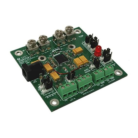
40 WATT UNIVERSAL
STEREO AUDIO
AMPLIFIER
Ramsey Electronics Model No.
Need more audio "punch" for a project? Build your own
powered speaker or juice up that audio kit with this high quality
audio amp. 40 Watts of awesome output for any application!
•
2 x 21W Output Power in Stereo Mode (8Ω, THD = 10%)
•
1 x 42W Output Power in Mono Mode (4Ω, THD = 10%)
•
High Efficiency: Up to 87%
•
Filterless Class D Amplifier
•
Unique Patented Spread-Spectrum Mode
•
Programmable Gain (+22dB, +25dB, +29.5dB, +36dB)
•
Balanced or Unbalanced High Impedance Inputs
•
Shutdown and Mute Control
•
Integrated Click-and-Pop Suppression
•
Low 0.1% THD+N
•
Current Limit and Thermal Protection
•
Programmable Thermal Flag
UAM4• 1
UAM4
Advertisement
Table of Contents
Troubleshooting

Related Manuals for Ramsey Electronics UAM4

Summary of Contents for Ramsey Electronics UAM4
- Page 1 40 WATT UNIVERSAL STEREO AUDIO AMPLIFIER Ramsey Electronics Model No. UAM4 Need more audio “punch” for a project? Build your own powered speaker or juice up that audio kit with this high quality audio amp. 40 Watts of awesome output for any application! •...
- Page 2 Ramsey Electronics publication No. UAM4 Rev. 1.6 This Printing: November 2007 COPYRIGHT 2007 by Ramsey Electronics, LLC, 590 Fishers Station Drive, Victor, New York 14564. All rights reserved. No portion of this publication may be copied or duplicated without the written permission of Ramsey Electronics, LLC.
-
Page 3: Table Of Contents
Manual Price Only $5.00 KIT ASSEMBLY AND INSTRUCTION MANUAL FOR 40 Watt Universal Stereo Audio Amplifier TABLE OF CONTENTS Introduction to the UAM4........4 How It Works ............. 4 “Learn-As-You-Build” Kit Assembly....8 SMT Soldering............ 9 Parts List............10 Pre-Assembly ..........10 Assembly Steps.......... -
Page 4: Introduction To The Uam4
HOW IT WORKS The UAM4 is a class D amplifier. The letter D is simply the next letter after C, and does not stand for digital. Class D and Class E amplifiers are sometimes mistakenly described as "digital"... - Page 5 MAX9708 and aside from a transistor, LED and zener diode, it is the major active component in the UAM4. The input signal(s) are applied to the left and right inputs at the right side of the schematic. These inputs have the advantage of being able operate in either balanced or un-balanced modes.
- Page 6 That’s it as far as the basic operation of the UAM4. But what about all those other components on the schematic? Well lets take a look at them! Most of them are used to configure the MAX9708.
- Page 7 ‘INPUT MODE’. This is a jumper, H3, used to set up for either stereo or mono mode. If is not installed the UAM4 will be in stereo mode. The left and right channels are independent and operate as two separate amplifiers.
-
Page 8: Learn-As-You-Build" Kit Assembly
MAX9708. Again, if you want more in depth information about the MAX9708 go to “www.maxim-ic.com” and locate the data sheet. RAMSEY Learn-As-You-Build KIT ASSEMBLY There aren’t that many solder connections on the UAM4 printed circuit board, but you should still practice good soldering techniques. •... -
Page 9: Smt Soldering
Notice also that when reheating the solder that the iron tip does not come in contact with the “tab” on the body of the chip component. Over heating of this solder tab can cause a fracture of the bond to the component, causing an intermittent connection. UAM4• 9... -
Page 10: Parts List
Pre-Assembly Make sure to check that all components are present and identify them before starting to assemble your UAM4. The small capacitors are not marked and are in separate packages with each value in its own pack. Be careful and don’t remove them from their package until you are ready to install them, as it... -
Page 11: Assembly Steps
(The OptiVisor in the Ramsey Catalog) to assemble and troubleshoot equipment. You’d be surprised what you can’t see on boards like the UAM4 without them! Position the board in front of you with the word ‘TOP’ readable in the upper right hand corner. - Page 12 These are large components and will be a cinch to install now that you’re an expert! 21. Install 10uF capacitor C12 near the left edge of the board (marked 106). 22. Install 10uF capacitor C17 (marked 106) near R7 on the left of the board. UAM4• 12...
- Page 13 36. Install 3 pin header H4, located along the right edge of the board. 37. Install 3 pin header H5, located along the right edge of the board. 38. Install 3 pin header H6, located along the right edge of the board. UAM4• 13...
- Page 14 See the picture below for more detail. JUMPER Once again check over all of your work. Check that all components are placed properly and there are no solder bridges between components and traces. That’s all folks!!! (For the assembly that is…) UAM4• 14...
-
Page 15: Using Your Uam4
INPUT SETUP First we need to set up the UAM4 for either stereo or mono input. If you are going to be using your UAM4 as a stereo, (two input signals) amplifier continue reading the “STEREO INPUT” steps below. If you are going to use the UAM4 as a mono (one input signal) amplifier, go to the “MONO INPUT”... - Page 16 ‘JUMPER FOR MONO’ located above and between the input connectors J1 and J2. Your UAM4 may be used in one of two mono out modes. You may use it as a simple 40 amplifier or you may use it as if it is two 20 watt amplifiers with a common input.
- Page 17 If you are going to use your UAM4 as a stereo amplifier then you will be using both the left and right channel inputs. If you are using your UAM4 as a mono amplifier either as a single 40 watt amplifier or as two 20 watt amplifiers you will use only the right channel input in the following steps.
-
Page 18: Uam4 Schematic
UAM4 SCHEMATIC DIAGRAM UAM4• 18... - Page 19 UAM4• 19...
- Page 20 Your speakers are going to be connected to the speaker output terminals J6, J7, J8, and J9. If you are using your UAM4 as a stereo amplifier keep reading. If you are operating your UAM4 in mono mode, go to the “MONO SPEAKER CONNECTION”...
-
Page 21: Detailed Input/Output Information
DUAL 20 WATT MONO OPERATION SPEAKER CONNECTIONS In the dual 20 watt mono configuration the UAM4 is actually set up as two 20 watt amplifiers with a common input which is applied to the right input terminals. This means that the ‘LFT+’ and ‘LFT-’ are the output of one 20 watt amplifier output and the ‘RT+’... - Page 22 40 watts of output at 18 volts. When the UAM4 was being developed, we used a supply with less than 1 amp capacity and it still gave us plenty of power for initial testing purposes (plus helped...
- Page 23 **STEREO Audio Gain Selection Jumpers ‘H4’ and ‘H5’ set the UAM4 gain. The input signal level will determine how these are configured. If you are wondering just what ‘dB’ is, it stands for ‘decibels’ and it is a unit of measure for sound intensity or level. To give a very simple explanation, every 3dB of voltage gain represents an output voltage increase of 1.4 times the input voltage.
- Page 24 **+36 Auto Shutdown Mode Selection The UAM4 provides a feature that allows it to be either muted or put in a shutdown state by applying a low to either the ‘MUTE’(J4) or ‘SHUTDOWN’(J3) connectors. These features can also be used in conjunction with the temperature sensing feature of the MAX9708 amplifier.
-
Page 25: Troubleshooting Guide
‘OVER TEMP’ that will light if this condition occurs. This signal can be used to either mute or put the UAM4 in shutdown mode as explained in the previous section. This threshold is set at the factory for 100 degrees C and this should be acceptable for most applications. -
Page 26: Troubleshooting Guide
**200(SSM) TROUBLESHOOTING If you find that your UAM4 is not functioning as expected the first thing to do is make sure there are no solder bridges between components and board traces. Since most of the components in this kit are surface mount and some are placed very close to each other there is a good possibility a bit of solder has found its way to the wrong place. - Page 27 (Be very careful when checking with the pin - some of the traces on the UAM4 board are so small that a simple poke with a pin could actually break...
- Page 28 However if you are using the UAM4 with an input signal such as a pure sine wave or in an enclosure where the ambient temperature is high, it is possible the threshold may need to be adjusted.
-
Page 29: Neat-To-Know Info
When a changing electrical current (like an audio signal from the UAM4, for instance) is applied to the coil a changing magnetic field is produced in the coil which interacts with the magnetic field of the magnet and the coil moves, thus moving the paper. -
Page 30: Conclusion
As our customers, we value your opinions, comments, and additions that you would like to see in future publications. Please submit comments or ideas to: Ramsey Electronics, LLC Attn. Hobby Kit Department 590 Fishers Station Drive Victor, NY 14564 or email us at: techsupport@ramseyelectronics.com... -
Page 31: Specifications
80, 90, 100, 110, 120, 129, 139, 150 Dimensions: Board 2.6in x 2.6in x .6in Corner mounting 4 ea .125 diameter spaced 2.2in x 2.2in x 2.2in x 2.2in Aux heat sink 2 ea .125in diameter spaced 1.075in apart UAM4• 31... -
Page 32: Uam4 Parts Layout Diagram
UAM4 BOARD PARTS LAYOUT DIAGRAM UAM4• 32... - Page 33 NOTES ______________________________________________________________ ______________________________________________________________ ______________________________________________________________ ______________________________________________________________ ______________________________________________________________ ______________________________________________________________ ______________________________________________________________ ______________________________________________________________ ______________________________________________________________ ______________________________________________________________ ______________________________________________________________ ______________________________________________________________ ______________________________________________________________ ______________________________________________________________ ______________________________________________________________ ______________________________________________________________ ______________________________________________________________ ______________________________________________________________ ______________________________________________________________ ______________________________________________________________ ______________________________________________________________ ______________________________________________________________ ______________________________________________________________ ______________________________________________________________ ______________________________________________________________ ______________________________________________________________ ______________________________________________________________ ______________________________________________________________ ______________________________________________________________ UAM4• 33...
- Page 34 NOTES ______________________________________________________________ ______________________________________________________________ ______________________________________________________________ ______________________________________________________________ ______________________________________________________________ ______________________________________________________________ ______________________________________________________________ ______________________________________________________________ ______________________________________________________________ ______________________________________________________________ ______________________________________________________________ ______________________________________________________________ ______________________________________________________________ ______________________________________________________________ ______________________________________________________________ ______________________________________________________________ ______________________________________________________________ ______________________________________________________________ ______________________________________________________________ ______________________________________________________________ ______________________________________________________________ ______________________________________________________________ ______________________________________________________________ ______________________________________________________________ ______________________________________________________________ ______________________________________________________________ ______________________________________________________________ ______________________________________________________________ ______________________________________________________________ UAM4• 34...
-
Page 35: Ramsey Kit Warranty
“1K ohm” resistors are actually the “missing” 10 K parts ("Hum-m-m, I guess the orange band really does look red!") Ramsey Electronics project kits are packed with pride in the USA by our own staff personnel. - Page 36 QUICK REFERENCE Introduction to the UAM4........4 Parts List............10 Assembly Steps..........11 Using Your UAM4..........15 UAM4 Schematic..........18 Troubleshooting Guide ........26 Specifications ........... 31 UAM4 Parts Layout Diagram......32 REQUIRED TOOLS • Soldering Iron • Thin Rosin Core Solder •...
Need help?
Do you have a question about the UAM4 and is the answer not in the manual?
Questions and answers