
Summary of Contents for base engineering FHSTP Series
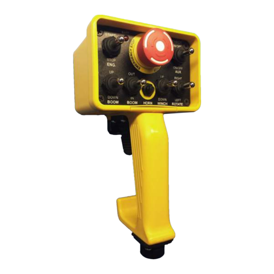
- Page 1 INSTALLATION AND OPERATING INSTRUCTIONS DSST SYSTEM PROPORTIONAL and NON-PROPORTIONAL TOGGLE SWITCH RADIO REMOTE CONTROL SYSTEM FHSTP/DSSTP MODEL SERIES...
- Page 2 It is strongly recommended that any radio control system be powered only when the equipment is parked and ready to work. A park-brake interlock switch for all air-brake truck applications is available from BASE Engineering at the time of order. April 2012 DSST Installation Guide, Rev. 5...
-
Page 3: System Operation
SYSTEM OPERATION General Operation Operation of the system requires that 12/24VDC power be applied to the receiver module. In most cases, this is done by connecting the RED wire on Cable 1 to a keyed, fused 12/24VDC source. After the switch is on, the BLUE light on the receiver will go ON solid. At this point the receiver is fully operational and is waiting for commands from the handheld unit. - Page 4 Note: The A2B and Pressure Switch options are not available on all systems. These options must be custom ordered. Please contact the factory for more information. Handheld Auto Shutoff The handheld unit has an auto shutoff feature that will turn off the handheld after a period of use.
-
Page 5: System Installation
SYSTEM INSTALLATION Receiver Module Select a suitable location for mounting of the receiver unit. The plastic enclosure, when properly installed is very resistant to water and other industrial contaminants. The receiver can be mounted anywhere on the equipment as long as there is an open, unobstructed path for the radio signal to reach the receiver/antenna. - Page 6 System Programming The DSST Wireless Control System is supplied from the factory fully programmed and ready for use, however, the following procedures can be used to re-program a replacement handheld or receiver unit if the field, as well as modifying minimum and maximum proportional output speeds.
- Page 7 b. Press the programming button on the receiver quickly 2 times. The blue LED should blink 2 times in confirmation. If pressed the incorrect number of times, the middle red LED will blink quickly 3 times. Repeat this step. c. The minimum speed can now be adjusted by the SETUP toggle on the handheld (top left position of...
- Page 8 Make sure there is power to the charger socket. o Make sure the correct charger is being used, i.e. the Li-ION battery charger from Base Engineering Inc. (12/24 volts) o Make sure the red LED on the outside of the charger lights when plugged in. If not, replace the charger fuse.
- Page 9 When pressing a toggle, both the red and blue LED’s flash simultaneously. o This indicates the trigger is pressed before the toggle. Release the trigger. If not pressed, move the trigger back and forth to check to see if it is stuck. Try the function again.
- Page 10 1.800.924.1010 For further details and product support please contact BASE Engineering Inc. @ BASE ENGINEERING INC. 600 ROTHESAY AVENUE SAINT JOHN NEW BRUNSWICK CANADA E2H 2H1 PHONE 1.800.924.1010 FAX 506.635.2281 E-MAIL SALES@BASENG.COM WWW.BASENG.COM FCC Rules and Compliance. This device complies with Part 15 of the FCC Rules. Operation is subject to the following two conditions: i.
Need help?
Do you have a question about the FHSTP Series and is the answer not in the manual?
Questions and answers