Table of Contents
Advertisement
Quick Links
Advertisement
Table of Contents

Subscribe to Our Youtube Channel
Summary of Contents for JAMA M8
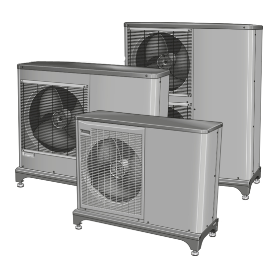
- Page 1 Installer manual JÄMÄ Inverter M8, M12, M16 Air/water heat pump...
-
Page 3: Table Of Contents
Table of Contents 1 Important information Connections Safety information 6 Commissioning and adjusting 2 Delivery and handling Preparations Filling and venting the heating medium sys- Transport and storage Assembly Compressor heater Supplied components Start-up and inspection Removing the covers Readjusting, heating medium side Removing the front panel Adjustment, charge flow Removing the side panel... -
Page 4: Important Information
1 Important information Safety information Serial number The serial number for JAMA Inverter can be found on the This manual describes installation and service proced-ures side of the foot. for implementation by specialists. JAMA Inverter M8 This appliance can be used by children... - Page 5 JAMA Inverter M16 Serial number Caution Always give the product's serial number when reporting a fault. Country specific information Installer manual This installer manual must be left with the customer. Chapter 1 | Important information...
- Page 6 Fill in the page for information about installation data in the User manual. Description Notes Signature Date ✔ System flushed System vented Particle filter Shut-off and drain valve Charge flow set Fuses property Safety breaker Communication cable connected JAMA Inverter addressed (only when cascade connection) Miscellaneous Chapter 1 | Important information...
- Page 7 Contact information Kaukora Oy PL 21, Tuotekatu 11 21200 Raisio Puh. 02 4374 600 E-mail kaukora@kaukora. www.kaukora. Chapter 1 | Important information...
-
Page 8: Delivery And Handling
Transport and storage JAMA Inverter must be transported and stored vertically. Assembly Place JAMA Inverter outdoors on a solid level base that can take the weight, preferably a concrete foundation. If concrete slabs are used they must rest on asphalt or shingle. - Page 9 Condensation run off Drain pan heater, control The drain pan heater is supplied with power when one of Condensation water trough the following conditions is met: The condensation water trough is used to collect and lead 1. Operating mode "Heating" or "Hot water" is activ- away condensation water from the heat pump.
-
Page 10: Supplied Components
Installation area The distance between JAMA Inverter and the house wall must be at least 150 mm. Clearance in front of JAMA Inverter should be at least one metre. Chapter 2 | Delivery and handling... -
Page 11: Removing The Covers
Removing the covers JAMA Inverter M8 JAMA Inverter M12/JAMA Inverter M16 Removing the front panel JAMA Inverter M8 Chapter 2 | Delivery and handling... -
Page 12: Removing The Side Panel
Removing the side panel JAMA Inverter M12 JAMA Inverter M12 JAMA Inverter M16 JAMA Inverter M16 Chapter 2 | Delivery and handling... -
Page 13: The Heat Pump Design
3 The heat pump design General JAMA Inverter M8 PWB2 PWB3 PWB1 BT12 63H1 FM01 BT15 QM35 QM36 EB11 EB10 GQ10 Chapter 3 | The heat pump design... - Page 14 JAMA Inverter M12 PWB3 PWB1 PWB2 63H1 FM01 BT12 BT15 EB11 EB10 GQ10 QM35 QM36 Chapter 3 | The heat pump design...
- Page 15 JAMA Inverter M16 PWB2 PWB3 PWB1 FM01 63H1 QM35 QM36 BT12 FM02 BT15 EB11 GQ10 EB10 Chapter 3 | The heat pump design...
- Page 16 Chapter 3 | The heat pump design...
- Page 17 List of componentsJAMA Inverter M8, M12, M16 Cable, incoming supply Pipe connections Service valve, liquid side QM35 Service valve, gas side QM36 Connection, heating medium out of JAMA Inverter, G3/4" (Ø22 mm) Connection, heating medium in to JAMA Inverter, G3/4" (Ø22 mm) Sensors etc.
-
Page 18: Electrical Connection
Electrical connection JAMA Inverter M8 Electrical components Communication board AA23 Dipswitch communication card AA23-S2 Terminal block, incoming supply AA23-X1 Terminal block, communication AA23-X4 Compressor heater EB10 (CH) EB11 (DH) Drip tray heater AA23 Main fuse compressor unit Fuse for external heating cable (250 mA), AA23-S2 max 45 W. - Page 19 JAMA Inverter M12 PWB3 PWB1 EB11 EB10 AA23 AA23-S2 AA23-X4 FM01 AA23-X1 PWB2 Chapter 3 | The heat pump design...
- Page 20 JAMA Inverter M16 PWB3 PWB1 AA23 AA23-S2 AA23-X4 EB11 EB10 FM01 AA23-X1 PWB2 Chapter 3 | The heat pump design...
-
Page 21: Pipe Connections General
Flow l/s Water volumes When docking with JAMA Inverter free flow in the climate -EB101 system is recommended for correct heat transfer. This can be achieved by use of a bypass valve. If free flow cannot... - Page 22 JAMA Inverter M8 JAMA Inverter M12 Heat insulation Heat insulation Chapter 4 | Pipe connections...
-
Page 23: Docking Alternatives
Docking alternatives JAMA Inverter M16 JAMA Inverter can be installed in several different ways. The requisite safety equipment must be installed in accord- ance with current regulations for all docked options. See kaukora.fi for more docking options. Connecting accessories Instructions for connecting accessories are in the install-ation instructions provided for the respective accessory. -
Page 24: Electrical Connections General
"C" (compressor operation). For MCB size see "Technical Specifications". AA23 JAMA Inverter does not include a circuit breaker on the in- coming power supply. The heat pump’s supply cable (W1) AA23-S2 must be connected to a circuit-breaker with at least a 3 mm breaking gap. - Page 25 JAMA Inverter M12 JAMA Inverter M16 PWB3 PWB1 PWB3 PWB1 AA23 AA23-X4 AA23 FM01 AA23-X4 FM01 PWB2 PWB2 Chapter 5 | Electrical connections...
-
Page 26: Connections
To prevent interference, unscreened commu- nication and/or sensor to external connections cables must not be laid closer than 20 cm to high voltage cables when cable routing. Power connection JAMA Inverter M8 Power connection Incoming supply Chapter 5 | Electrical connections... - Page 27 JAMA Inverter M12 Power connection Incoming supply Chapter 5 | Electrical connections...
- Page 28 JAMA Inverter M16 Incoming supply Power connection Incoming supply cable (W1) is supplied and factory connected to terminal block X1. Approx. 1.8 m cable is accessible outside the heat pump. Connect communication cable (W2) (provided by in- staller) to terminal block AA23-X4 and secure with two cable ties, see image.
- Page 29 JAMA Inverter M16 JAMA Inverter M8 Cables for communication (W2) are routed through ferrite beads/ EMI filters. Secure the communication cable (W2) here using two cable ties. JAMA Inverter M12 Secure the communication cable (W2) here using two cable ties.
- Page 30 External heating cable KVR 10 (Accessory) Cable routing The following images show recommended cable rout-ing JAMA Inverter is equipped with a plinth for external from the distribution box to the condensation water pipe. heating cable EB14 not supplied). The connection is fused Route the heating cable (EB14) through the grommet with 250 mA (F3 on the communication board AA23).
- Page 31 JAMA Inverter M16 ation address is selected for JAMA Inverter to JAMA control module. Default has JAMA Inverter address 1. In a cascade connection all JAMA Inverter must have a unique address. The address is coded in binary. Secure the heating cable...
-
Page 32: Commissioning And Adjusting Preparations
2. Vent the system using the venting nipple (QM20) on the enclosed flexible hose and possibly the cir- culation pump. Compressor heater JAMA Inverter is equipped with a compressor heater that heats the compressor before start-up and when the com- pressor is cold. NOTE The compressor heater must have been con- nected for 6 –... -
Page 33: Start-Up And Inspection
This is done by switching on the control voltage and disconnecting the communication AA23-S2 cable. 2. JAMA Inverter must be addressed if it is to have another address than 1. See chapter Addressing via AA23-X4 cascade connection, on page 29. -
Page 34: Readjusting, Heating Medium Side
JAMA Inverter M12/JAMA Inverter M16 AA23 AA23-S2 AA23-X4 Caution Do not start any electrical work until at least two minutes after cutting the power. Readjusting, heating medium side Air is initially released from the hot water and venting may be necessary. If bubbling sounds can be heard from the heat pump, the circulation pump and radiat-ors the entire system will require further venting. -
Page 35: Adjustment, Charge Flow
Instructions for adjusting hot water charging are in the installation manual for the respective indoor section. See page 38 for the list of the indoor sections and ac-cessories that can be used with JAMA Inverter. Chapter 6 | Commissioning and adjusting... -
Page 36: Disturbances In Comfort Troubleshooting
JAMA Inverter communicates all alarms to the indoor module. In the event of action to rectify malfunctions that require work within screwed hatches the Ensure that the JAMA Inverter is connected to the power incoming electricity must isolated at the safety source. - Page 37 Sensor placement Connection to card (PWB1) JAMA Inverter M8 EB10 EB11 63H1 FM01 PWB1 Chapter 7 | Disturbances in comfort...
- Page 38 JAMA Inverter M12/JAMA Inverter M16 Connection to card (AA23) 63H1 EB11 EB10 FM01 Tho-R2 BT16 BT14 BT17 BT28 Sensor placement in JAMA Inverter Tho-R1 Tho-D Tho-S Tho-A JAMA Inverter M8, M12 Sensors etc. Current sensor BE1 (CT) Defrost/Cooling High pressure pressostat...
- Page 39 Data for return line temperature sensor (BT3), con-densor supply (BT12) and fluid pipe (BT15) Data for sensor in JAMA Inverter Tho-D Temperature Resistance Voltage (VDC) (kΩ) (°C) (kOhm) 351.0 3.256 251.6 3.240 182.5 3.218 133.8 3.189 99.22 3.150 74.32 3.105 56.20...
-
Page 40: Accessories
8 Accessories Condensation water pipe Wall mounting Condensation water pipe,different Wall mounting JAMA Inverter M8 lengths. Wall mounting JAMA Inverter M12 Earth circuit breaker 1-phase. KVR 10-10 JAMA Inverter 1 metre Water heater/Accumulator tank BUFFER 100 KVR 10-30 JAMA Inverter Part no. -
Page 41: Technical Data
9 Technical data Dimensions and setting-out coordinates JAMA Inverter M8 Adjustable 40-50 1035 Ø40* * Accessory KVR 10 is required. JAMA Inverter M12 Adjustable 40-50 1075 1145 Ø40* * Accessory KVR 10 is required. Chapter 9 | Technical data... - Page 42 JAMA Inverter M16 Adjustable 40-50 1075 1145 Ø40* * Accessory KVR 10 is required. Free space behind Fritt utrymme bakom 600 mm Minimum free Free space in Minimum free Min. distance when using Min. avstånd space front space dning several JAMA Inverter...
- Page 43 The sound pressure levels are further affected by walls, bricks, differences in ground level, etc and should JAMA Inverter is usually placed next to a house wall, therefore only be seen as guide values. which gives a directed sound distribution that should be JAMA Inverter adjusts the fan speed depending on the considered.
-
Page 44: Coordinates Sound Pressure Levels
Technical specifications Air-water heat pump Heating Outd. temp: / Nominal Nominal Nominal Supply temp. 7/35 °C (floor) 3.85/0.84/4.60 5.12/1.08/4.74 7.22/1.55/4.66 Output data according to EN14511 ΔT5K 2/35 °C (floor) 6.03/1.59/3.79 6.77/1.74/3.89 9.58/2.53/3.78 Specified/supplied power/COP (kW/kW/-) -7/35 °C (floor) 5.91/2.08/2.84 7.95/2.69/2.96 10.79/3.76/2.87 2/55 °C 4.35/2.03/2.14... -
Page 45: Technical Specifications Electrical
Air-water heat pump Min flow, climate system, at 100% circulation 0.19 0.29 0.39 pump speed (defrosting flow) Min flow, heating 0.12 0.15 0.25 Min flow, cooling 0.15 0.20 0.32 Max/Min heating medium temp continuous op- °C 58/25 eration Connection heating medium ext thread G1"... - Page 46 Working range, compressor operation - heating JAMA Inverter M8, M12. M16 Water temperature °C Supply temperature Return temp Outdoor air temperature °C During shorter time it is allowed to have lower working temperatures on the water side, e.g. during start up.
-
Page 47: Circuit Diagram
Electrical circuit diagram JAMA Inverter M8 Chapter 9 | Technical data... - Page 48 (4A) INV PWB2 EB10 EB11 BP2 LPT BT16 BT14 BT17 BT28 Tho-P Tho-D Tho-S 63H1 Tho-R1 Tho-A Chapter 9 | Technical data...
- Page 49 JAMA Inverter М12 Chapter 9 | Technical data...
- Page 50 Y/GN F (30A) F (8A) NOISE FILTER PWB3 -AA23 -X100 F (4A) FM01 FM02 Note Do not connect any wires on the port1 on TB. − + 4 3 2 1 4 3 2 1 7 6 5 4 1 7 6 5 4 1 CNW2 CNEEV1...
- Page 51 JAMA Inverter М16 Chapter 9 | Technical data...
- Page 52 Y/GN F (30A) F (8A) NOISE FILTER PWB3 F (4A) FM01 FM02 + 4 3 2 1 4 3 2 1 7 6 5 4 1 7 6 5 4 1 CNW2 CNEEV1 CNEEV2 CNFAN1 CNFAN2 (BK) (OR) (WH) (RD) (WH) (WH) CNI2...
-
Page 53: Item Register
10 Item register Item register Inspection of the installation, 4 Accessories, 38 Installation area, 8 Addressing via multi-heat pump operation, 29 Adjustment, charge flow, 33 Marking, 2 Ambient temperature sensor, 29 Assembly, 6 Pipe connections, 19 Docking alternatives, 21 Commissioning and adjusting, 30 General, 19 Adjustment, charge flow, 33 Pipe coupling heating medium circuit, 19... - Page 55 Kaukora Oy PL 21, Tuotekatu 11 21200 Raisio Puh. 02 4374 600 E-mail kaukora@kaukora. www.kaukora.
Need help?
Do you have a question about the M8 and is the answer not in the manual?
Questions and answers