Advertisement
Quick Links
RESIDENTIAL INSTALLATION
MANUAL FOR SOLAR POOL HEATING
Before attempting installation, read these instructions and acquaint yourself with the component names.
Great care has been taken to make this an easy-to-follow procedure. A little time spent understanding
the system and its parts will assure a successful, trouble-free installation.
CAUTION: SAFETY COMES FIRST
When working on or around your roof or pool, please take care to avoid hazards such as electrical wires and
loose shingles. If you have any product or installation questions, contact your Heliocol representative.
UMA Solar | © 2020
Advertisement

Related Manuals for Magen eco-Energy UMA Solar Heliocol

Summary of Contents for Magen eco-Energy UMA Solar Heliocol
- Page 1 RESIDENTIAL INSTALLATION MANUAL FOR SOLAR POOL HEATING Before attempting installation, read these instructions and acquaint yourself with the component names. Great care has been taken to make this an easy-to-follow procedure. A little time spent understanding the system and its parts will assure a successful, trouble-free installation. CAUTION: SAFETY COMES FIRST When working on or around your roof or pool, please take care to avoid hazards such as electrical wires and loose shingles.
-
Page 2: Pre-Installation Notes
INTRODUCTION Heliocol solar collectors are manufactured utilizing state-of-the-art solar technology and the most advanced production techniques. Heliocol collectors are sleek and simple, yet the patented over-molded design makes Heliocol durable enough to last a lifetime. However, a professional installation is very important to the overall success of a system. Installed properly, a Heliocol System will be virtually maintenance free as it captures free, abundant, and reliable energy from the sun year after year. - Page 3 PRE-INSTALLATION NOTES (CONTINUED) While this manual explains how to install Heliocol solar collectors properly in typical situations, it cannot possibly address all the unique or individual circumstances possible. If you have any installation questions, contact your Heliocol representative for assistance. Before starting any work, determine the location of your system and prepare a schematic drawing of the installation area.
-
Page 4: Required Tools And Materials
REQUIRED TOOLS & MATERIALS DEPENDING UPON THE NATURE OF THE INSTALLATION, YOU WILL NEED OTHER TOOLS, PLUMBING ITEMS, AND MATERIALS SUCH AS: TOOLS ELECTRICAL COMPONENTS • Screwdriver(s) • Wire Ties • Power Drill & Driver(s) • Wire Nuts • Pipe Cutter •... - Page 5 SYSTEM DESIGN & SIZING For pool heating applications the design and sizing of systems is relatively simple and is a function of several factors including pool size, location, and orientation. What follows is a walkthrough of the design and sizing process for solar pool heating systems. SYSTEM SIZING For most pool heating applications, the optimal system size will be 75-100% of the pool surface area.
- Page 6 SYSTEM DESIGN & SIZING (CONTINUED) ROOF ANCHOR SPACING Fig. 1 HELIOCOL RESIDENTIAL INSTALLATION MANUAL...
- Page 7 SYSTEM DESIGN & SIZING (CONTINUED) COLLECTOR CONFIGURATIONS There are many ways to configure a solar pool heating system using Heliocol collectors. The most common and preferred method is in a single, continuous row, or bank of collectors. Bank sizing is limited by the size and quantity of Heliocol collectors used to achieve even flow throughout the bank.
- Page 8 SYSTEM DESIGN & SIZING (CONTINUED) For larger systems or where the roof design presents a challenge multiple banks may be used. For more information on this please see the section Collector Layout & Plumbing later in this manual. Roof obstacles like vents, stacks, or skylights may also require multiple banks to be used.
- Page 9 SYSTEM DESIGN & SIZING (CONTINUED) PUMP & FLOW RATE Many solar pool heating systems will employ the existing pool filtration pump to supply flow to the solar collectors via a manual or motorized diverter valve. In these configurations the water will flow through the solar collectors after exiting the filter before returning to the pool instead of going to the pool directly.
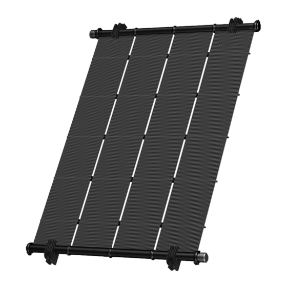
- Page 10 THE SOLAR COLLECTOR Heliocol collectors are comprised of two manifolds overmolded onto a quantity of separate riser tubes held in place by spacer bars on the underside of the collector. Each riser tube represents a full flow path for water from one manifold to the other. As a finished unit Heliocol collectors have the ability to accept and heat a large volume of water efficiently with very little head loss.
- Page 11 THE SOLAR COLLECTOR (CONTINUED) HC-50 Solar Insolation Category T(°F) 2,000 BTU/ft 1,500 BTU/ft 1,000 BTU/ft A (-9) 101.28 77.17 57.88 B (+9) 48.23 28.94 9.65 C (+36) 4.82 D (+90) Thousands of BTU’s per day per panel HC-40 Solar Insolation Category T(°F) 2,000 BTU/ft 1,500 BTU/ft...
-
Page 12: Installation Kits
INSTALLATION KITS The following is a description of the installation kits that are required for a complete Heliocol installation. The System Kit and Collector Kit are always required while the Row Spacer Kit is only required for certain installations. The Pressure Test Kit is used at the end of the installation to test the system while the Repair Tool Kit is used if you ever need to repair a collector. - Page 13 COMPONENTS TABLE 5 ITEM # DESCRIPTION HC-0110 SHORT HC-0110 SHORT HC-0110 LONG ALLIGATOR CLAMP ALLIGATOR CLAMP ALLIGATOR CLAMP 2-1060-001 Bottom Gator Clamp 2-1060-002 Top Gator Clamp 2-1060-001 2-1060-002 2-1810-003 End Cap 2-1810-020 Panel Clamp Top 2-1810-015 Panel Clamp Bottom 2-1810-018 Panel Clamp Latch 2-1810-003 2-1810-020...
- Page 14 COLLECTOR LAYOUT & PLUMBING Collectors can be installed in a multitude of configurations and methods, but systems should adhere to a few key rules for optimal performance. Systems that are pitched should be installed with the feed line(s) entering the collector bank(s) on the lower manifold and the return lines exiting the banks(s) on the opposite, upper manifold end.
- Page 15 COLLECTOR LAYOUT & PLUMBING (CONTINUED) Fig. 2.1 - SINGLE ROW Fig. 2.2 - DOUBLE ROW Fig. 2.3 - SINGLE ROW SPLIT FEED HELIOCOL RESIDENTIAL INSTALLATION MANUAL...
- Page 16 COLLECTOR LAYOUT & PLUMBING (CONTINUED) END CAP END CAP END CAP END CAP RETURN FEED END CAP END CAP Fig. 6.4 - SERIES FEED FIGURE 5.4 RETURN FEED SERIES FEED Fig. 2.4 - SERIES FEED FIGURE 5.4 SERIES FEED END CAP END CAP END CAP END CAP...
- Page 17 CONNECTING COLLECTORS TOGETHER Fig. 3 Place two collectors next to each other. The spacer bars that hold the individual riser tubes together should be facing down. Lay a plastic collector clamp top, bottom, gasket, and latch where the two manifolds meet. (Fig. 3-A) Clean the groove of both manifolds.
- Page 18 CONNECTING COLLECTORS TOGETHER (CONTINUED) Seat both manifolds together by inserting the gasket into the opposite manifold groove and placing the ends of both manifolds into the open space in the collector clamp bottom. (Fig. 3-D) Interlock the top half of the collector clamp with the hook on the bottom half. Swing top half over top of collector manifolds.
- Page 19 COLLECTOR ROOF MOUNTING – SHINGLE ROOFS Panel Header (Top) Top Panel Clamp L Latch Gasket Bottom Panel Clamp Top Gator Clamp Bottom Gator Clamp Fig. 4 NOTE: A secure, permanent connection to the roof is important to the performance and longevity of the Heliocol system.
- Page 20 COLLECTOR ROOF MOUNTING – SHINGLE ROOFS (CONTINUED) The vast majority of residential roofing in the US is asphalt shingle roofing. For the purposes of this manual only installations for asphalt shingle roofs will be detailed in depth. Snap a chalk line across the roof or rack where you want the top edge of the collectors to be located.
- Page 21 COLLECTOR ROOF MOUNTING – SHINGLE ROOFS (CONTINUED) To ensure proper spacing between the upper and lower mounting points, hang the top manifolds of the collectors in the bottom portion of the Gator Clamps attached to the roof as you go. Once again, be sure Gator Clamps are at least 2” away from each ridge along the header.
- Page 22 COLLECTOR ROOF MOUNTING – SHINGLE ROOFS (CONTINUED) Peel off the protective paper and firmly press the RT-Mini onto the roof making sure the butyl sealant has adequate contact with the roof surface. Slide the stainless steel ¼-20 hex bolt into the top slot in the RT-Mini. (Fig. 6-A) If mounting into the roof truss install the (2) included M5 x 60 mm (#10 x 2.375”) wood screws through the two holes in the center of the mount.
- Page 23 COLLECTOR ROOF MOUNTING – OTHER ROOFS While pitched, asphalt shingle roofs make up most of the roofing in the US there are a variety of other roofs types that may be encountered in the field. Concrete tile, metal, and low-slope roofing are less common but are still able to support Heliocol systems.
- Page 24 ROOF OBSTACLES ROOF OBSTACLES UP TO 6” WIDE: Roof obstacles up to 6” wide (small vents or stacks) may be circumvented by unsnapping the riser tubes from the spacer bar and spreading them out to allow the obstruction to pass through the risers. Obstructions must be less than, or equal to, 6”...
- Page 25 ROOF OBSTACLES (CONTINUED) ROW SPACER APPLICATION (Roof Obstacles Greater Than 6” Wide): PPC ASSEMBLY PPC ASSEMBLY 1 1/2” PVC PIPE CPVC PIPE CPVC PIPE CONNECTOR CONNECTOR Fig. 10.1 Fig. 8 Connect (4) of the CPVC Pipe Connectors to the manifolds of the collectors with PPC sets using the same procedures outlined in the section on Connecting Collectors Together.
- Page 26 CONTROLLING THERMAL DEFORMATION PIPING Thermal deformation (expansion & contraction) occurs in all materials subject to change in temperature. Piping will expand & contract in all directions, but the greatest change will occur with the length of the pipe. Very long pipe runs subject to a large change in temperatures during the year will require controls for thermal deformation designed in.
- Page 27 ROOFTOP PLUMBING HEADER END CAP PPC ASSEMBLY CPVC PIPE CONNECTOR 1 ½” PVC STUB Fig. 11 The feed line will be connected to one end of the bottom manifold, which should preferably be the corner farthest from the pool equipment. The return line will be connected to the top manifold on the opposite end of the bank.
- Page 28 ROOFTOP PLUMBING (CONTINUED) Attach the CPVC Pipe Connectors to the corners of the bank where the feed and returns lines will be using the PPC sets. (Fig. 12-B). All four manifold ends should have either an end cap or CPVC Pipe Connector attached. •...
- Page 29 INTERMEDIATE PLUMBING The following procedure represents the most straightforward way of plumbing the system from the pool equipment to the collectors. While every installation is unique there are a few aspects that should always be included: • Whenever possible, the return line should have the shortest run between the collectors and the pool equipment.
- Page 30 INTERMEDIATE PLUMBING (CONTINUED) Fig. 13 HELIOCOL RESIDENTIAL INSTALLATION MANUAL...
- Page 31 CONNECTING TO THE POOL EQUIPMENT Vacuum Breaker TO SOLAR RETURN FROM COLLECTOR SOLAR COLLECTOR (Cool) (Warm) TO ROOF SENSOR Pressure Test Kit Auto Control used here to pressure test the system (OPTIONAL) Ball Valve Valve Actuator Ball Valve Wire TO POOL Three Way Valve SENSOR Non-Positive Seal...
- Page 32 CONNECTING TO THE POOL EQUIPMENT (CONTINUED) Fig. 14 shows how a typical Heliocol solar pool heating system is plumbed into existing pool plumbing. While the pool equipment may not always be configured exactly as shown it illustrates the key points for interconnecting the solar pool heating system to pool’s filtration loop.
- Page 33 CONNECTING TO THE POOL EQUIPMENT (CONTINUED) Plumb the solar feed line to one of the ports on the 3-way diverter valve. A two-way isolation valve should also be plumbed into the feed line after the diverter valve in an accessible location at the pool equipment area. If installing the vacuum relief valve on the feed line, a PVC tee and ¾”...
- Page 34 AUTOMATIC CONTROL SYSTEMS IF USING AN AUTOMATIC CONTROL SYSTEM TO CONTROL THE SOLAR POOL HEATING SYSTEM, FOLLOW THESE ADDITIONAL STEPS: Follow all instructions outlined in the installation manual of the automatic control system being used. Install the actuator motor onto the three-way diverter valve and wire it to the controller per manufacturer instructions.
-
Page 35: Pressure Testing
PRESSURE TESTING Upon completion of the installation of a solar pool heating system the system should be pressure tested to verify that all connections are sound and watertight. The system should be tested to 40-50 PSI to ensure proper installation. Wrap the threads of the Pressure Test “T”... - Page 36 OPERATION & CHECKOUT PROCEDURES BEFORE WATER IS RUN THROUGH THE SYSTEM: Allow the cemented fittings adequate time to dry per manufacturer’s instructions. Verify that all check valves, control valves, and vacuum relief valves are installed properly. Verify that all Plastic Panel Clamps are properly assembled and seated. Pressure test the system as detailed in this manual.
- Page 37 OPERATION & CHECKOUT PROCEDURES (CONTINUED) MANUAL SYSTEMS: TURNING THE SYSTEM ON Turn the pool pump off. Turn the three-way diverter valve so the “closed” indicator points toward the pool return side of the valve. Be sure that the isolation valves on the feed and return lines are open. Turn the pool pump on.
- Page 38 OPERATION & CHECKOUT PROCEDURES (CONTINUED) MANUAL SYSTEMS: TURNING THE SYSTEM OFF Turn the pool pump off. Turn the three-way diverter valve so the “closed” indicator points toward the solar feed side of the valve. If isolating the collectors, close the isolation valve on the feed & return lines after you are sure all the water has drained out of the collectors and plumbing.
-
Page 39: Troubleshooting
TROUBLESHOOTING PROBLEM CAUSE SOLUTION THERE ARE AIR BUBBLES IN 1. If the pump is making more noise, A. Be sure pump trap lid is on tight. THE POOL WHEN THE SOLAR there may be air coming into the HEATER IS OPERATING pump through an air leak on the B. - Page 40 TROUBLESHOOTING (CONTINUED) PROBLEM CAUSE SOLUTION SOME OF THE SOLAR PANELS 1. There is not equal flow through all A. Be sure filter is clean. Backwash ARE WARM TO THE TOUCH of the panels. Warm panels indicate to reduce pressure. WHILE OTHERS ARE COOL TO low water flow.
- Page 41 TROUBLESHOOTING (CONTINUED) PROBLEM CAUSE SOLUTION THE AREA LEAKS BETWEEN 1. PPC latch is not tight enough to Slide the latch farther across the THE HEADERS AT THE PLASTIC seal the joint. connection between top and bottom PANEL CLAMPS half of the clamp. 2.
- Page 42 RISER TUBE REPAIR PROCEDURE THE HELIOCOL SOLAR COLLECTOR IS A VERY DURABLE PRODUCT, BUT THERE ARE A FEW STEPS YOU SHOULD TAKE TO PROTECT ITS LONGEVITY. • Try to avoid walking on the collectors. If you cannot avoid it, always wear soft-soled shoes. •...
- Page 43 RISER TUBE REPAIR PROCEDURE (CONTINUED) Pull out the rubber insert tool. Using your fingers or channel-lock pliers, push a poly-insert into the rubber insert as far as you can. Cut the riser tube to the desired length and slide it over the stub of the poly-insert for a straight, eye-pleasing fit.
- Page 44 FOR ANY QUESTIONS OR ISSUES PLEASE CONTACT YOUR UMA SALES REPRESENTATIVE HELIOCOL RESIDENTIAL INSTALLATION MANUAL...
- Page 45 DISTRIBUTED BY: 800.79.SOLAR • www.umasolar.com...
Need help?
Do you have a question about the UMA Solar Heliocol and is the answer not in the manual?
Questions and answers