
Related Manuals for Miller XMS 44


Summary of Contents for Miller XMS 44
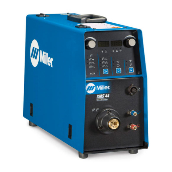
- Page 1 OM-223 839H 2014−03 Processes MIG (GMAW) Welding Flux Cored (FCAW) Welding Description Wire Feeder XMS 44 Wire Feeder OWNER’S MANUAL Visit our website at www.MillerWelds.com...
- Page 2 From Miller to You Thank you and congratulations on choosing Miller. Now you can get the job done and get it done right. We know you don’t have time to do it any other way. That’s why when Niels Miller first started building arc welders in 1929, he made sure his products offered long-lasting value and superior quality.
-
Page 3: Table Of Contents
TABLE OF CONTENTS SECTION 1 − SAFETY PRECAUTIONS - READ BEFORE USING ........1-1. - Page 4 ITW Welding Products Italy S.r.l Via Privata Iseo 6/E, 20098 San Giuliano M.se, (MI) Italy declares that the product(s) identified in this declaration conform to the essential requirements and provisions of the stated Council Directive(s) and Standard(s). Product/Apparatus Identification: Product Stock Number XMS 44 029007424 Council Directives: • 2006/95/EC Low Voltage •...
-
Page 5: Section 1 − Safety Precautions - Read Before Using
SECTION 1 − SAFETY PRECAUTIONS - READ BEFORE USING som 2013−09 Protect yourself and others from injury — read, follow, and save these important safety precautions and operating instructions. 1-1. Symbol Usage DANGER! − Indicates a hazardous situation which, if Indicates special instructions. - Page 6 D Remove stick electrode from holder or cut off welding wire at FUMES AND GASES can be hazardous. contact tip when not in use. D Wear body protection made from durable, flame−resistant material Welding produces fumes and gases. Breathing (leather, heavy cotton, wool). Body protection includes oil-free these fumes and gases can be hazardous to your clothing such as leather gloves, heavy shirt, cuffless trousers, high health.
-
Page 7: Additional Symbols For Installation, Operation, And Maintenance
1-3. Additional Symbols For Installation, Operation, And Maintenance FIRE OR EXPLOSION hazard. MOVING PARTS can injure. D Do not install or place unit on, over, or near D Keep away from moving parts such as fans. combustible surfaces. D Keep all doors, panels, covers, and guards D Do not install unit near flammables. -
Page 8: California Proposition 65 Warnings
1-4. California Proposition 65 Warnings Welding or cutting equipment produces fumes or gases This product contains chemicals, including lead, known to which contain chemicals known to the State of California to the state of California to cause cancer, birth defects, or other cause birth defects and, in some cases, cancer. -
Page 9: Section 2 − Definitions
SECTION 2 − DEFINITIONS 2-1. Additional Safety Symbols And Definitions Some symbols are found only on CE products. Warning! Watch Out! There are possible hazards as shown by the symbols. Safe1 2012−05 Do not discard product (where applicable) with general waste. Reuse or recycle Waste Electrical and Electronic Equipment (WEEE) by disposing at a designated collection facility. -
Page 10: Miscellaneous Symbols And Definitions
Do not weld on drums or any closed containers. Safe64 2012−06 Do not remove or paint over (cover) the label. Safe20 2012−05 Drive rolls can injure fingers. Safe32 2012−05 Welding wire and drive parts are at welding voltage during operation − keep hands and metal objects away. Safe33 2012−05 Wear hat and safety glasses. -
Page 11: Section 3 − Introduction
SECTION 3 − INTRODUCTION 3-1. Important Information Regarding CE Products (Sold Within The EU) This equipment shall not be used by the general public as the EMF limits for the general public might be exceeded during welding. This equipment is built in accordance with EN 60974−1 and is intended to be used only in an occupational environment (where the general public access is prohibited or regulated in such a way as to be similar to occupational use) by an expert or an instructed person. -
Page 12: Remote 7 Receptacle Information
Ref. 956142646-3-A DOWN 0V/10V digital signal TYPE 0V/10V digital signal Remote 7 This remote receptacle cannot be used with a standard Miller remote control. A customer supplied remote control is required to use the remote receptacle. 3-6. 14-Pin Plug Information Pin* Pin Information 24 volts AC with respect to socket G. -
Page 13: Connecting Welding Gun
3-7. Connecting Welding Gun Gun Securing Screw Gun Block Gun Outlet Wire Guide Loosen knob, insert gun into block. Position outlet wire guide as close as possible to drive rolls without touching. Tighten knob. Gun Trigger Plug Gun Trigger Receptacle Contact manufacturer equipment needed to connect... -
Page 14: Installing Wire Guide And Drive Roll
3-8. Installing Wire Guide And Drive Roll Inlet Wire Guide Intermediate Wire Guide Install and secure inlet wire guide, and intermediate wire guide. Drive Roll (4) Install drive rolls and turn drive roll 1−2 nut one click. During maintenance intervals, remove drive rolls, and clean grooves using a wire brush. -
Page 15: Circuit Protection
3-9. Circuit Protection Circuit Breaker CB1 Circuit breaker CB1 is located in- side the wire feeder as shown. CB1 Protects the auxiliary 24 volt AC circuit from overload. 956142646-6-B 3-10. Connecting Wire Feeder to Power Source Make connections as shown. Be sure connections are tight. -
Page 16: Changing Cable Between Wire Feeder And Xms 403
3-11. Changing Cable Between Wire Feeder and XMS 403 Disconnect power before changing cables. Access Door Clamp Plastic Collar Connect weld cable to terminals be- hind access door. Remove screws securing door, clamp and collar. Make cable con- nections. Reinstall clamp, collar, and door. -
Page 17: Section 4 − Operation
SECTION 4 − OPERATION 4-1. Control Panel MIG Gun Connector Red Quick Connect Fitting (Coolant Return From Gun). Blue Quick Connect Fitting (Coolant Output To Torch) Remote Control Receptacle Handle Panel D1 − (Display 1) Displays values and parameters for selected welding process. -
Page 18: Switching On Unit And Recalling Factory Parameters
4-2. Switching On Unit And Recalling Factory Parameters Install power source and wire feeder ac- D1 and D2 will show hyphens. When MIG Turn power source Off then On again. Im- cording to supplied Owner’s Manuals. Turn welding, wire feeder is always on. Displays mediately press wire feeder P1 and P3. -
Page 19: Trigger Mode Selection
4-4. Trigger Mode Selection When trigger is pressed, welding starts. When trigger is pressed a second time, Always check and set a trigger mode. welding continues at level 2 parameters. If trigger mode is undefined for a weld- When trigger is released, welding stops. When trigger is released the second time, ing process, select the desired mode. -
Page 20: Setup Menu
4-6. Setup Menu Press P2 to enter SET UP menu. E1 changes the welding parameter. Incorrect settings in any process can Setup allows viewing and changing default result in a program with undesirable E2 changes the parameter value. parameter values for all welding processes weld characteristics. -
Page 21: Preparing Unit For Mig Welding
4-9. Preparing Unit For MIG Welding To select MIG welding process, pro- ceed as follows: Follow safety precautions according to Section NO TAG. Prepare unit according to Section 3. Using a cable with a proper adapter, connect gun to the MIG gun connector. -
Page 22: Selecting Manual Mig Welding
4-10. Selecting Manual MIG Welding Set Manual MIG welding process on the power source. L6 is On. Higher inductance setting produces a softer weld puddle and less spatter, but arc starts may be more difficult. Lower induc- In Manual MIG mode, the operator may need to adjust main welding tance setting produces a stiffer weld puddle and more spatter, parameters for specific arc characteristics. -
Page 23: Selecting Synergic Mig Welding
4-11. Selecting Synergic MIG Welding Set Synergic MIG welding process on the If necessary, use P2 to adjust the welding Setting Inductance power source. L7 is ON. parameters. Press P2 to enter SET UP menu. Purge air from gun hose using P3 push but- In Synergic MIG mode, the operator may Use E1 to select on D1 ind. -
Page 24: Selecting Synergic Pulsed Mig Welding
4-12. Selecting Synergic Pulsed MIG Welding Set Synergic Pulsed MIG welding process on the Setting Main Welding Regulation teristics produce a better weld bead appearance power source. L7 is On. especially on aluminum. The Synergic Double See Section 4-11. Pulsed MIG process allows control all parame- Synergic Pulsed MIG welding is a high quality ters to produce high quality welds on aluminum. -
Page 25: Section 5 − Maintenance & Troubleshooting
Drive Vacuum Inside Rolls 5-2. Help Displays The XMS 44 microprocessor controls all internal parameters of the Verify that the motor and cabling are functioning. units. HLP 104 In case of failure, D1 and D2 will show the following Error Signals. -
Page 26: Troubleshooting
5-3. Troubleshooting Problem Solution Unit is completely inoperative. Check continuity of Power switch S1, and replace if necessary. Reset circuit breaker CB1 if open. Check input power source. See welding power source Technical Manual. Wire does not feed, unit completely inop- Turn Power switch On. -
Page 27: Section 6 − Electrical Diagram
SECTION 6 − ELECTRICAL DIAGRAM 956142626C OM-223 839 Page 23... -
Page 28: Section 7 − Parts List
SECTION 7 − PARTS LIST Hardware is common and not available unless listed. Fig. 6-2 Ref. 956142646-1-B Figure 7-1. Main Assembly OM-223 839 Page 24... - Page 29 Item Dia. Part Mkgs. Description Quantity Figure 7-1. Main Assembly ..... V57052030 . . . Euro Adapter ..........
- Page 30 Hardware is common and not available unless listed. Ref. 956142646-2-B Figure 7-2. Wire Drive Assembly OM-223 839 Page 26...
- Page 31 Item Dia. Part Mkgs. Description Quantity Figure 7-2. Wire Drive Assembly ....V57010029 . . . Motor 24 VDC, 60 W ........
- Page 32 Table 6-1. Drive Roll And Wire Guide Kits (4 Drive Roll) Base selection of drive rolls upon the following recommended usages: 1. V-Grooved rolls for hard wire. 2. U-Grooved rolls for soft and soft shelled cored wires. 3. U-Cogged rolls for extremely soft shelled wires (usually hard surfacing types). 4.
- Page 33 Notes...
- Page 34 Notes...
- Page 35 Effective January 1, 2014 (Equipment with a serial number preface of ME or newer) This limited warranty supersedes all previous Miller warranties and is exclusive with no other guarantees or warranties expressed or implied. LIMITED WARRANTY − Subject to the terms and conditions 90 Days —...
- Page 36 File a claim for loss or damage during Phone: 39 (0) 2982901 Fax: 39 (0) 298290-203 shipment. email: miller@itw−welding.it For assistance in filing or settling claims, contact your distributor and/or equipment manufacturer’s Transportation Department. © ORIGINAL INSTRUCTIONS − PRINTED IN USA 2014 Miller Electric Mfg. Co. 2014−01...
Need help?
Do you have a question about the XMS 44 and is the answer not in the manual?
Questions and answers