Table of Contents
Advertisement
Quick Links
Applications
The SGF104 has been introduced by Duomo at the
request of architects and consultants to provide a more
architecturally discrete enclosure without compromi-
sing the sensitivity of detection. Other sensors within
the SGF100 range sense Natural Gas, Carbon Monoxide,
Freon, Hydrogen Sulphide, Hydrogen and LPG.
The SGF104 is used to monitor levels of oxygen in
locations such as:
•
Research & Teaching Laboratories,
•
Food & Manufacturing,
•
Electronics assembly clean rooms.
Where a risk, for example, of Nitrogen (or any inhert
gas) leaking may reduce oxygen content within an
enclosed environment.
Operation
The SGF104 senses either a reduction or an increase in
levels of of oxygen. It provides a signal proportional to
the levels of oxygen to either a Duomo central control
from the GS or BX range or directly to Building Mana-
gement Systems.
i
Before connecting the unit careful reading of instruction booklet is recommended,
and it is kept in a safe place for future reference. Furthermore, the correct electrical
connections according to the enclosed drawings, complying with instructions.
Installation and user guide
SGF 104 Oxygen Sensor
• Oxygen sensor
• 4-20mA output
• Senses depletion or Excess O
• Compatible with Duomo controllers*
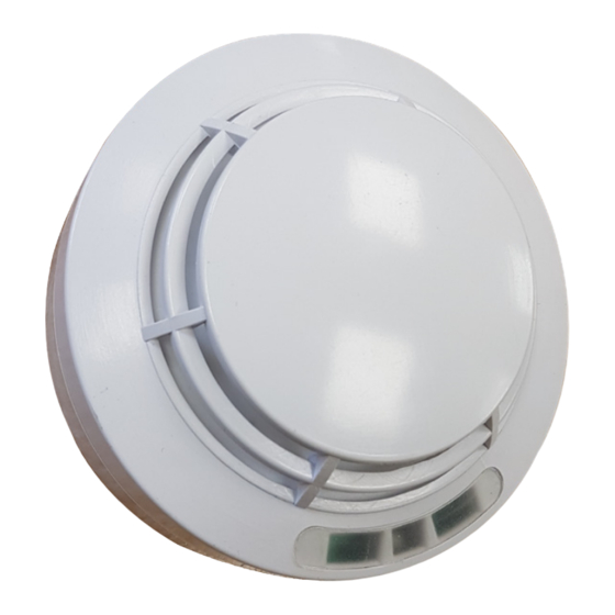
• Architecturally discrete Gas sensor
• Ceiling or wall mounted
• Status indication lights
• Conforms to EN50104 and EN50270
• 12 to 24V DC supply
• Relay output 1A @ 30V DC
• IP64 Protective rating
The SGF104 Oxygen Depletion sensor has a range of
0-25% Oxygen. The system is normally set to give a
first stage warning alarm at 19.0% Oxygen, and then a
second stage full alarm at 17.0%. This enables action to
be taken before an evacuation is required and evacua-
tion before a dangerous situation arises. Excess Oxyen
levels can be monitored and an alarm relay activated
at 22.5 or 23.5%.
Features
The self-calibration facility allows the probe to adapt
in difficult environments and variable temperatures
helping to avoid false alarms.
By connecting a datalogging and diagnostic tool
(Duomo TS1007) to the sensor It is possible to read
back sensor history and other individual sensor specific
information, such as:
•
Sensor serial number,
•
Date of manufacture,
•
Number of power ups,
•
Number of alarms,
•
Number of days of anticipated
sensor life remaining
Firmware Version 1.0
2
Advertisement
Table of Contents

Related Manuals for Duomo SGF 104


Summary of Contents for Duomo SGF 104
- Page 1 By connecting a datalogging and diagnostic tool enclosed environment. (Duomo TS1007) to the sensor It is possible to read back sensor history and other individual sensor specific Operation information, such as: The SGF104 senses either a reduction or an increase in •...
- Page 2 Technical Specification Power supply ........................12÷24 VDC ± 10% Power demand ..................110 mA in alarm Max @ 13,8 VDC Relay switching alarm ......................1 A 30VDC SELV Selection of positive safety..................Selectable by switch Type of gas detected: Oxygen Integrated sensor according to the type of gas ............Optical fluorescence Operating range of the sensing element ................0 - 25 % of O Operating range selectable by switch .......
- Page 3 Assembly of three parts of the SGF’s Series sensor Backplate supplied with SGF Series Sensors OPTIONAL Socket connection with cable gland for external mounting on demand Art. ZSGF100 Socket assembly. Place the probe as in the drawing, and rotate in clockwise direction WARNING! Actions to be taken in case of alarm Oxygen “O2”...
- Page 4 Sensor Status indication Operating LED Green: Operating Red: Flashing: detecting gas or Steady: alarm threshold exceeded. Yellow: Fault Connections and P.C.B. Layout Detection data memory through USB port Switch 1 - Selection of positive safety R - + C NC NO Connect the sensor to the TS1007 and read the data transmitted.
- Page 5 Positioning of the Sensor The positioning of the sensor is an important factor for the correct function of the gas detection control unit. In order to obtain the best results and minimize the probabilities of false alarms, we recommend following this diagram and to keep in mind the following general rules. The probe should be placed at a height of about 1.60 cm from the ground, if the height of the room is higher than 2.8m it is recommended to install it at an average height between ceiling and floor.
- Page 6 Sensor Output relative to Oxygen content in Air - % vol. 19.4 18.4 17.4 16.5 15.8 25.0 %vol 18,5 19,5 20,9 22,5 23,5 Current-Voltage Conversion Graph with 220 Ohm Load Resistance Linear +/-5% 0,88 1,1 Troubleshooting before calling a technician If the device does not start up.
- Page 7 Electrical Connections WARNING Before connecting to the power, ensure the voltage is correct. Carefully follow the instructions and the connections according to local regulations. For optimum performance connect using Screened cable earthed at one end. Avoid running sensor cable close to any power cabling. Relay max 1A Power supply 30 VDC SELV...
- Page 8 Defects caused by unauthorized personnel tampering, incorrect installation and negligence resulting from phenomena outside normal functioning shall be excluded from the warranty. DUOMO Ltd is not liable for possible damage, direct or indirect, to people, animals, or things; from DISPOSAL OF OLD ELECTRICAL & ELECTRONIC EQUIPMENT.
Need help?
Do you have a question about the SGF 104 and is the answer not in the manual?
Questions and answers