Table of Contents
Advertisement
Quick Links
Advertisement
Table of Contents

Related Manuals for MMF KSI84 Series


Summary of Contents for MMF KSI84 Series
- Page 1 Instruction Manual 4-20 mA Vibration Sensor Type KSI84xx v1.32.030 Manfred Weber Metra Mess- und Frequenztechnik in Radebeul e.K. Meissner Str. 58 - D-01445 Radebeul Tel. +49-351 836 2191 Fax +49-351 836 2940 Email: Info@MMF.de Internet: www.MMF.de...
- Page 2 Metra Mess- und Frequenztechnik in Radebeul e.K. Meißner Str. 58 D-01445 Radebeul Tel. 0351-836 2191 0351-836 2940 Email Info@MMF.de Internet www.MMF.de Note: The latest version of this document can be found at: https://www.mmf.de/product_literature.htm All rights reserved, including those of translation.
-
Page 3: Table Of Contents
Contents 1 Purpose .....................4 2 Function ....................4 3 Type Selection ..................5 3.1 Frequency Range (HP, LP) ..............5 3.2 Measuring Range ................6 3.3 Type Code ..................6 4 Sensor Operation ..................7 4.1 Sensor Mounting .................7 4.2 Sensor Connection ................7 4.2.1 Connection to the Loop Supply ..........7 4.2.2 Sensor Cable ................8 4.2.3 Grounding Concept ..............8 4.3 Connection of the Measuring Device ..........9... -
Page 4: Purpose
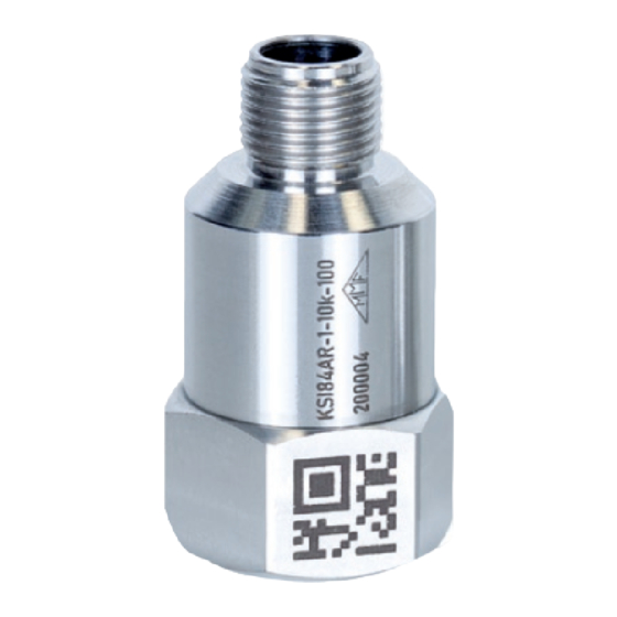
Purpose The vibration sensors of the KSI84xx family are used to measure vibration acceleration or velocity on machines and objects. The sensors measure the vibration amplitude within a specified frequency range in axial sensor direction and outputs the measuring result as a 4-20 mA current loop signal. -
Page 5: Type Selection
Either the acceleration (without integration) or the velocity (with integration) of the vibration can be measured. In addition, proper sensor function and input signal are monitored. Defects or overloads are signaled by an error current value. Before delivery, the sensor is parameterized according to the type code selected by the customer. -
Page 6: Measuring Range
The HP filter of velocity sensor types has a stopband attenuation of -50 dB/decade, the LP filter has a stopband attenuation of - 40 dB/decade. Frequency response 3.2 Measuring Range The “Range” value in the type table corresponds to the measured value at which the sensor current is 20 mA. -
Page 7: Sensor Operation
Sensor Operation 4.1 Sensor Mounting The choice of an appropriate measuring point on the target is important for accurate vibration measurement. It can be helpful to consult a specialist in machine moni- toring for this purpose. In general, it is advisable to measure vibrations as near as possible to their source. This minimizes errors by transmitting mechanical components. -
Page 8: Sensor Cable
4.2.2 Sensor Cable We recommend to use shielded cable for best EMI protection. The cable shield has be connected to earth potential at one end (see 4.2.3). Metra offers the following connection accessory: Type 080G/W: Binder 713, female, straight (G) or angled (W) with screw terminals for connection an existing sensor cable;... -
Page 9: Connection Of The Measuring Device
4.3 Connection of the Measuring Device The following figures show possibilities to measure the sensor current. + PIN 2 + PIN 2 + PIN 2 KSI84xx KSI84xx KSI84xx - PIN 3 - PIN 3 - PIN 3 The sensor current can be measured either directly by a current meter connected in series or indirectly by measuring the voltage drop across the load resistance R between PIN 3 and the negative terminal. -
Page 10: Sensor Self-Test
4.4 Sensor Self-Test The sensor starts with a self-test once it is connected to the loop supply voltage. During self-test, the sensor outputs the maximum sensor current of 22 mA and the offset current of 4 mA for a duration of 2 seconds. These currents can be measured with an ampere meter to ensure proper function. -
Page 11: Offset Current And Noise
4.5.3 Offset Current and Noise The offset current I of the sensor is 4 mA. This is the zero point in measuring mode. The calibrated value is output while sensor elf-test for control. A slightly larger current value is measured when no vibration excitation is present, the current in rest. -
Page 12: Maximum Dynamic Range
4.5.5 Maximum Dynamic Range The maximum dynamic range is the maximum peak amplitude value that can be processed without overdriving the signal processing. For accelerometers, the maximum dynamic range is independent of frequency. For all velocity sensors, the maximum dynamic range depends on the frequency. It is halved when the frequency doubles. -
Page 13: Settling Time T
4.7.2 Settling Time T The averaging filter causes a signal delay. If the vibration signal changes abruptly, the sensor signal only changes smoothly. The signal change is not completed until the settling time T has elapsed. The table below shows the relationship between the number of averages N and the minimal settling time T. -
Page 14: Error Messages
4.9 Error Messages If the sensor current is between 4 mA and 22 mA, the sensor is in normal operational mode. Any current outside this range indicates a specific error. The following table shows the values used. Current Error Cause Remedy LOOP The sensor cannot... -
Page 15: Technical Data
Technical Data 5.1 Technical Characteristics of the 4-20mA Signal Conditioning Sensor system Piezoelectric accelerometer Measured quantity according to type code KSI84Ax-x-x-x Acceleration m/s² KSI84Vx-x-x-x Velocity mm/s Mode according to type code KSI84xR-x-x-x KSI84xP-x-x-x PEAK ... pk Linear frequency range according to type code High pass filter -3dB... -
Page 16: Type Tables
5.5 Type Tables 5.5.1 Acceleration, RMS Range Type code Noise m/s² m/s² KSI84AR-1-LP-10 0.005 KSI84AR-1-LP-20 0.005 KSI84AR-1-LP-50 0.007 KSI84AR-1-LP-100 0.007 KSI84AR-1-LP-200 0.008 KSI84AR-1-LP-500 0.016 KSI84AR-1-5k-10 0.020 KSI84AR-1-5k-20 0.020 KSI84AR-1-5k-50 0.030 KSI84AR-1-5k-100 0.060 KSI84AR-1-5k-200 0.080 KSI84AR-1-5k-500 0.160 KSI84AR-1-10k-20 0.050 KSI84AR-1-10k-50 0.090 KSI84AR-1-10k-100 0.180 KSI84AR-1-10k-200... -
Page 17: Acceleration, Peak
5.5.2 Acceleration, PEAK Range Type code Noise m/s² pk m/s² pk KSI84AP-1-LP-10 0.005 KSI84AP-1-LP-20 0.005 KSI84AP-1-LP-50 0.007 KSI84AP-1-LP-100 0.007 KSI84AP-1-LP-200 0.008 KSI84AP-1-LP-500 0.016 KSI84AP-1-5k-10 0.020 KSI84AP-1-5k-20 0.020 KSI84AP-1-5k-50 0.030 KSI84AP-1-5k-100 0.060 KSI84AP-1-5k-200 0.080 KSI84AP-1-5k-500 0.160 KSI84AP-1-10k-50 0.090 Peak KSI84AP-1-10k-100 0.180 KSI84AP-1-10k-200 0.200 KSI84AP-1-10k-500... -
Page 18: Velocity, Rms
5.5.3 Velocity, RMS Range Type code Noise mm/s mm/s KSI84VR-1-LP-40 0.100 300, 1k 50,8 KSI84VR-1-LP-50 KSI84VR-3-LP-20 25.4 KSI84VR-3-LP-25 0.035 KSI84VR-3-LP-40 50.8 KSI84VR-3-LP-50 KSI84VR-10-LP-10 12.7 KSI84VR-10-LP-12 KSI84VR-10-LP-20 0.010 25.4 KSI84VR-10-LP-25 KSI84VR-10-LP-40 50.8 KSI84VR-10-LP-50 KSI84VR-30-LP-10 12.7 KSI84VR-30-LP-12 KSI84VR-30-LP-20 0.005 25.4 KSI84VR-30-LP-25 KSI84VR-30-LP-40 50.8 KSI84VR-30-LP-50 Complies with the requirements of... -
Page 19: Limited Warranty
Limited Warranty Metra warrants for a period of 24 months that its products will be free from defects in material or workmanship and shall conform to the specifications current at the time of shipment. The warranty period starts with the date of invoice. The customer must provide the dated bill of sale as evidence.
Need help?
Do you have a question about the KSI84 Series and is the answer not in the manual?
Questions and answers