Table of Contents
Advertisement
Quick Links
Advertisement
Table of Contents

Subscribe to Our Youtube Channel
Related Manuals for Elation KL FRESNEL 6 FC


Summary of Contents for Elation KL FRESNEL 6 FC
- Page 1 KL FRESNEL 6 FC User Manual...
- Page 2 ©2022 ELATION PROFESSIONAL all rights reserved. Information, specifications, diagrams, images, and instructions herein are subject to change without notice. ELATION PROFES- SIONAL logo and identifying product names and numbers herein are trademarks of ELATION PROFESSIONAL. Copyright protection claimed includes all forms and matters of copyrightable materials and information now allowed by statutory or judicial law or hereinafter granted.
-
Page 3: Table Of Contents
CONTENTS General Information Limited Warranty Safety Guidelines Maintenance Guidelines Overview Installation Instructions Accessory Installation Remote Device Management (RDM) System Menu Encoder Knobs DMX Traits Color Temperature Table Virtual Colors Specifications Dimensional Drawings... -
Page 4: General Information
(approximately 12.5mm), but is NOT protected against liquid intrusion of any kind. CUSTOMER SUPPORT - Contact ELATION Service for any product related service and support needs. Also visit forums.elationlighting.com... -
Page 5: Limited Warranty
No accessories should be shipped with the product. If any accessories are shipped with the product, Elation Professional shall have no liability what so ever for loss and/or or damage to any such accessories, nor for the safe return thereof. -
Page 6: Safety Guidelines
This fixture is a sophisticated piece of electronic equipment. To guarantee smooth operation, it is important to follow all instructions and guidelines in this manual. Elation Professional is not responsible for injury and/or damages resulting from the misuse of this fixture due to the disregard of the information printed in this manual. - Page 7 SAFETY GUIDELINES DO NOT TOUCH the fixture housing during operation. DO NOT shake fixture, and avoid brute force when installing and/or operating fixture. DO NOT operate fixture if the power cord is frayed, crimped, damaged and/or if any of the power cord connectors are damaged or do not fit into the fixture securely with ease.
-
Page 8: Maintenance Guidelines
Regular inspections are recommended to ensure proper function and extended life. There are no user serviceable parts inside this fixture. Please refer all service issues to an authorized Elation service technician. Should you need any spare parts, please order genuine parts from an authorized Elation dealer. -
Page 9: Overview
OVERVIEW Carrying Handle Fuse 3-pin DMX In Service Port 3-pin DMX Out Power 5-pin DMX Out Power 5-pin DMX In Mounting Safety Bracket Cable Loop Bracket Adjustment Knob Zoom Knob Display Screen Enter Mode Down Control Button Button Button Button Knob... -
Page 10: Installation Instructions
INSTALLATION INSTRUCTIONS FLAMMABLE MATERIAL WARNING Keep fixture minimum 5.0 feet (1.5m) away from flammable materials and/or pyrotechnics. ELECTRICAL CONNECTIONS A qualified electrician should be used for all electrical connections and/or installations. MINIMUM DISTANCE TO OBJECTS/SURFACES IS 1 FOOT (0.3 METERS) MINIMUM DISTANCE TO FLAMMABLE MATERIALS IS 1.6 FEET (0.5 METERS) MAXIMUM AMBIENT OPERATING TEMPERATURE IS 113°... - Page 11 INSTALLATION RIGGING Overhead rigging requires extensive experience, including calculating working load limits, knowledge of installation material being used, and periodic safety inspection of all instal- lation material and the fixture, among other things. If you lack these qualifications, do not attempt the installation yourself.
- Page 12 INSTALLATION STAND MOUNTING This unit can also be installed atop a tripod stand. Simply insert the threaded bolt on the top of the tripod stand through the hole in the top of the mounting yoke. Tighten the nut onto the threaded bolt to secure the mounted device in place. CAUTION! MAKE SURE THAT THE TRIPOD LEGS AND ALL TELESCOPING ELEMENTS OF THE TRIPOD STAND...
- Page 13 LEDs. This issue is not unique to Elation lighting fixtures, but rather it is a common issue with lighting fixtures from all manufacturers. Although there is no true way to completely prevent this issue from occurring, the guidelines below can reduce the risk of any potential damage if followed.
-
Page 14: Accessory Installation
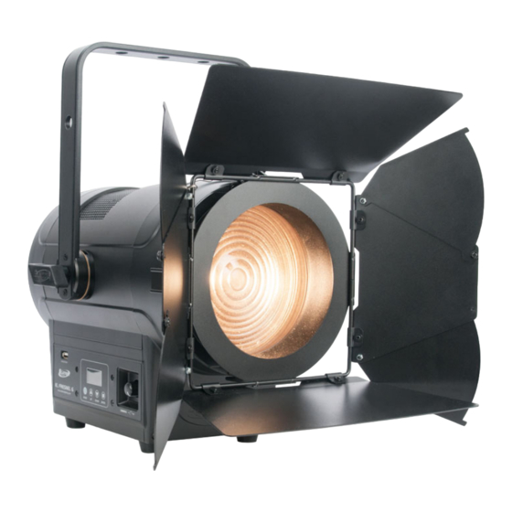
ACCESSORY INSTALLATION GEL FILTER This unit includes a gel filter accessory that can be installed or removed. To install, find the lens frame latch positioned at the top of the lens, press the locking mechanism to unlock the latch, and swing the latch upwards (below left). Then simply slide the gel frame into the lens frame (below right), making sure to use the frame slot that is closest to the lens. - Page 15 ACCESSORY INSTALLATION BARNDOORS This unit includes a barndoor accessory that can be installed or removed. To install, first find the lens frame latch located at the top of the lens frame. Press the locking mechanism to unlock the latch, then swing the latch upwards (below left). Slide the barndoor into an open lens frame slot (below middle).
-
Page 16: Remote Device Management (Rdm)
REMOTE DEVICE MANAGEMENT (RDM) NOTE: In order for RDM to work properly, RDM enabled equipment must be used through- out the entire system, including DMX data splitters and wireless systems. Remote Device Management (RDM) is a protocol that sits on top of the DMX512 data stan- dard for lighting, allowing the DMX systems of the fixtures to be modified and monitored remotely. -
Page 17: System Menu
SYSTEM MENU The fixture includes an easy to navigate system menu. The control panel display located on the side of the fixture (illustrated below) provides access to the main system menu where all necessary system adjustments are made to the fixture. •... - Page 18 SYSTEM MENU Disabled Dimmer ENCODER Int CCT Grn MODE Int Color Sat Manual Control DMX Address 001 - 512 1ch Dimmer 6ch Dimmer Color 11ch Standard DMX Mode 18ch Extended 9ch CMY SETTINGS 14ch CMY Extended Hold Last Defines reac- No DMX tion to loss or Fade to Black...
- Page 19 SYSTEM MENU LED Refresh 900-1500Hz, 2500Hz, 4000Hz, 5000Hz, Default = Rate 6000Hz, 10KHz, 15KHz, 20KHz, 25KHz 1200Hz LED Power Limit 100% Auto Fan Mode Silent High Screen re- turns to home page after Screen Delay 10s - 5min a period of inactivity;...
- Page 20 SYSTEM MENU Total run Life Time xxxxxx h hours. Not resettable Run hours Last Run Time xxxxxx h since last reset Reset run Time Reset Passcode = 038 hours Current temp Current reading Max temp Temperature Max Resettable since last INFORMA- reset TION...
-
Page 21: Encoder Knobs
ENCODER KNOBS This device features two encoder knobs that enable quick, convenient adjustment of various parameters. Please note that any DMX signal will override the encoder knob inputs. The loca- tions of the two encoder knobs are illustrated below: Zoom Knob Control Knob... -
Page 22: Dmx Traits
DMX TRAITS CHANNEL 14ch FUNCTION VALUES 11ch 18ch Dim. Dim. Ext. Color Ext. 000 - 255 Dimmer, 0% to 100% 000 - 255 Dimmer Fine Shutter, strobe 000 - 031 Shutter closed 032 - 063 No function (shutter open) 064 - 095 Strobe effect, slow to fast 096 - 127 No function (shutter open) 128 - 159 Pulse effect in sequences 160 - 191 No function (shutter open) - Page 23 DMX TRAITS CHANNEL 14ch FUNCTION 11ch 18ch VALUES Dim. Dim. Ext. Color Ext. Color Wheel Open Virtual Swatch Book (see Virtual Colors section 001 - 179 of this manual) Color Scroll 180 - 201 Clockwise, fast to slow 202 - 207 Stop 208 - 229 Counter-clockwise, slow to fast 230 - 234 Open Random Slots...
- Page 24 DMX TRAITS CHANNEL 14ch FUNCTION 11ch 18ch VALUES Dim. Dim. Ext. Color Ext. Dimmer Delay time (continued) 0.8s 0.9s 1.0s 1.5s 2.0s 3.0s 4.0s 5.0s 6.0s 7.0s 8.0s 9.0s 142 - 255 Idle Control 000 - 029 Idle 030 - 039 Fan Mode Auto 040 - 049 Fan Mode Silent 050 - 059 Fan Mode High 060 - 099 Idle...
- Page 25 DMX TRAITS CHANNEL 14ch FUNCTION 11ch 18ch VALUES Dim. Dim. Ext. Color Ext. Refresh Rates (continued) 1020 Hz 1030 Hz 1040 Hz 1050 Hz 1060 Hz 1070 Hz 1080 Hz 1090 Hz 1100 Hz 1110 Hz 1120 Hz 1130 Hz 1140 Hz 1150 Hz 1160 Hz...
- Page 26 DMX TRAITS CHANNEL 14ch FUNCTION 11ch 18ch VALUES Dim. Dim. Ext. Color Ext. Refresh Rates (continued) 1350 Hz 1360 Hz 1370 Hz 1380 Hz 1390 Hz 1400 Hz 1410 Hz 1420 Hz 1430 Hz 1440 Hz 1450 Hz 1460 Hz 1470 Hz 1480 Hz 1490 Hz...
-
Page 27: Color Temperature Table
COLOR TEMPERATURE TABLE DMX VALUE COLOR TEMP (K) DMX VALUE COLOR TEMP (K) 2400 5500 2500 5600 2600 5700 2700 5800 2800 5900 2900 6000 3000 6100 3100 6200 3200 6300 3300 6400 3400 6500 3500 6600 3600 6700 3700 6800 3800 6900... -
Page 28: Virtual Colors
VIRTUAL COLORS VALUE FILTER# COLOR VALUE FILTER# COLOR Pale Yellow Mauve Straw Medium Purple Gold Tint Lavender Spring Yellow Palace Blue Medium Yellow Dark Blue Yellow Medium Blue Deep Amber Deep Blue Deep Straw Daylight Blue Loving Amber Slate Blue Gold Amber Light Blue Orange... -
Page 29: Specifications
SPECIFICATIONS SOURCE 220W 6500K RGBMA LED Engine 50,000 Hour Average LED Life* *May vary depending on several factors including but not limited to: Environmental Conditions, Power/Voltage, Usage Patterns (On-Off Cycling), Control and Dimming. PHOTOMETRIC DATA 8,000 Total Lumen Output CRI 92.2 Zoom Range 10°... -
Page 30: Dimensional Drawings
DIMENSIONAL DRAWINGS FIXTURE ONLY 13.5in (344mm) 10.7in (272mm) 15.8in (401mm) Dimensions not drawn to scale. - Page 31 DIMENSIONAL DRAWINGS BARNDOOR ATTACHED (same as shown on previous page except where noted) 18.6in (472mm) 11.7in (298mm) 20.8in (529mm) Dimensions not drawn to scale.
Need help?
Do you have a question about the KL FRESNEL 6 FC and is the answer not in the manual?
Questions and answers