Table of Contents

Summary of Contents for AVL DITEST IRP 120
- Page 1 USER MANUAL IRP 120 / DCIR-PROBE INTERNAL RESISTANCE PROBE DIRECT CURRENT INTERNAL RESISTANCE PROBE ID number: AT7949EN Revision: Version: 05/22 Data subject to change. All data valid at the time of printing. PASSION INNOVATES FUTURE...
- Page 2 The contents of this publication, in whole or in part, may not be reproduced in any form or passed on to third parties without the prior written consent of AVL DiTEST. This publication was written exercising reasonable care. AVL DiTEST can therefore not accept any liability...
-
Page 3: Table Of Contents
Software ........................15 5.2.1 Software Installation ......................15 5.2.2 Software Update ........................16 Working with the IRP 120 ............... 17 Starting the IRP 120 ....................... 17 Self-Test ........................19 Module Internal Resistance Measurement ................22 6.3.1 Module Internal Resistance with One Module ..............24 6.3.2... - Page 4 IRP 120 Index ....................62...
-
Page 5: General
Intended Use INTERNAL RESISTANCE PROBE, referred to in the following as IRP 120, is used to measure the internal resistance of a battery module and the resistance between modules (busbar) of an electric vehicle (traction) battery. -
Page 6: Safety
Safety IRP 120 2 Safety This manual contains important warnings and safety instructions that require attention by the user. Non-compliance with these warnings may result in death or serious injury. Always follow the safety instructions on the screen. 2.1 Safety Instructions and Warning Signs... - Page 7 IRP 120 Safety Notes: Note This text refers to situations or operating errors that can lead to damage to property or data loss. Information This text refers to important information or instructions. Not following these instructions will significantly prevent or hinder the successful execution of the actions described in this documentation.
-
Page 8: Important Safety Instructions
IRP 120 Safety IMPORTANT SAFETY INSTRUCTIONS When using the product, a professional must ensure that the test object or test system cannot enter operating modes that could cause personal injury or material damage. 1. Read all instructions. 2. Do not use the device if it is damaged. Do not use it with damaged cables. Wait until a qualified service technician has inspected the device and/or cables. -
Page 9: Safety Concept
DANGER Risk of death from electric voltage on vehicles equipped with high-voltage systems Only use measuring equipment provided by AVL DiTEST. If using general measuring adapters (test probes, measuring clamps, etc.), make sure that they are suitable and approved for measuring and test voltages up to 1000 V and meet the EN 61010-31 standard. - Page 10 Risk of death due to electric voltage The product may only be repaired by the supplier plant or by trained specialists. Note The device may only be operated with accessories and consumables supplied by AVL DiTEST or approved by AVL DiTEST. User Manual...
-
Page 11: Scope Of Supply
IRP 120 Scope of Supply Scope of Supply Standard scope of supply: Part ID number IRP 120 BO7970 Current clamp cable, red BV8320 Current clamp cable, black BV8321 Test probe cables BV8319 Test probe, red EU8005 Test probe, black EU8006... -
Page 12: Assembly
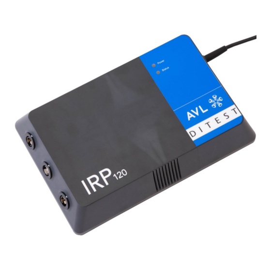
IRP 120 Assembly 4 Assembly 4.1 Overview The following illustration shows the configuration of the IRP 120: Fig. 1 IRP 120 measuring module Air vents LEDs USB cable, connection to PC Air vents Red connection, positive current clamp Blue connection, test probes... -
Page 13: Leds
IRP 120 Assembly 4.2 LEDs Power LED Status Sensor No power supplied to IRP 120. No light No connection to tester. Blue, continuously lit IRP 120 is ready for operation. IRP 120 is starting. Blue, flashing (Bootload procedure) Status LED... -
Page 14: Current Clamp Cable
DANGER Risk of death due to electric voltage The IRP 120 complies with the surge voltage values of the surge voltage category CAT-II 600 V / CAT-III 300 V. Do not conduct measurements on circuits connected directly to the mains. -
Page 15: Test Probe Cables
DANGER Risk of death due to electric voltage The IRP 120 complies with the surge voltage values of the surge voltage category CAT-II 600 V / CAT-III 300 V. Do not conduct measurements on circuits connected directly to the mains. - Page 16 DANGER Risk of death due to electric voltage The IRP 120 complies with the surge voltage values of the surge voltage category CAT-II 600 V / CAT-III 300 V. Do not conduct measurements on circuits connected directly to the mains.
-
Page 17: Commissioning
IRP 120 Commissioning Commissioning Hardware Connect the IRP 120 USB plug to a free USB port on the PC; see Fig. 5. Fig. 5 5.2 Software 5.2.1 Software Installation AVL DiTEST DSS Manager must be installed in order to use the IRP application. If AVL DiTEST DSS Manager is already installed, the IRP application can also be installed. -
Page 18: Software Update
Commissioning IRP 120 Fig. 6 4. Navigate to the IRP download area. If AVL DITEST DSS Manager is installed, install Install.IRPApplication.x.x.x.x.exe. If AVL DITEST DSS Manager is not installed, install Install.DSSManager+IRPApplication.x.x.x.x.exe 5.2.2 Software Update Updating the operating software used in the device takes place automatically via the PC. Make sure that the latest version of the operating software is installed on the PC. -
Page 19: Working With The Irp 120
IRP 120 Working with the IRP 120 Working with the IRP 120 Starting the IRP 120 Start the software by clicking Start│Programs│DiTEST│DSS. Click Diagnostics│IRP. Fig. 7 User Manual... - Page 20 Working with the IRP 120 IRP 120 A start screen appears. Fig. 8 User Manual...
-
Page 21: Self-Test
IRP 120 Working with the IRP 120 Self-Test If an error occurs, carry out a self-test first. To conduct a self-test, proceed as follows: Start│Programs│ 1. Start the software by clicking DiTEST│DSS. 2. Click Diagnostics│IRP. Fig. 9 A start screen appears. - Page 22 Working with the IRP 120 IRP 120 Click Selftest Fig. 10 4. Pay attention to the instructions on the screen and disconnect the cables shown. Fig. 11 5. The self-test is performed and the result is displayed. F8 Next to return to the start screen.
- Page 23 IRP 120 Working with the IRP 120 Fig. 12 User Manual...
-
Page 24: Module Internal Resistance Measurement
Working with the IRP 120 IRP 120 Module Internal Resistance Measurement To measure the internal resistance in a module, proceed as follows: 1. On the start screen, click Module internal resistance. Fig. 13 2. Enter the name of the test engineer and set a password. - Page 25 IRP 120 Working with the IRP 120 Fig. 14 4. Choose whether you are taking the measurement in one or three modules and click Next. Fig. 15 A screen opens where you can enter the test parameters. The following two chapters describe how to take a measurement using one or three modules.
-
Page 26: Module Internal Resistance With One Module
Working with the IRP 120 IRP 120 6.3.1 Module Internal Resistance with One Module This chapter describes how to measure the internal resistance using one module. 1. As described in Module Internal Resistance Measurement, navigate to the parameter entry screen. - Page 27 IRP 120 Working with the IRP 120 Fig. 17 Values that are too low are red Information Clicking Help makes it possible to display the automatically calculated parameter limits. Information The entered parameter limits can be saved by clicking Save and can then be retrieved from the drop-down menu.
- Page 28 Working with the IRP 120 IRP 120 4. Connect the positive (red) and negative (black) clamps as shown in the software. Information Clicking Placement opens a view of the exact placement of the individual components. Fig. 18 Probe connection overview...
- Page 29 IRP 120 Working with the IRP 120 Fig. 19 Placement of the clamp and measuring probes 5. Press and hold the button on the red test probe to start the measurement. 6. Connect the positive (red) and negative (black) test probe.
- Page 30 Working with the IRP 120 IRP 120 7. To stop measuring, let go of the test button. 8. Click Report to view the test report. If multiple measurements were taken, the test report is expanded to include each additional measurement. Click Edit to add comments.
-
Page 31: Module Internal Resistance With Three Module
IRP 120 Working with the IRP 120 6.3.2 Module Internal Resistance with Three Module To measure the internal resistance using three modules, proceed as described below. 1. As described in Module Internal Resistance Measurement, navigate to the parameter entry screen. - Page 32 Working with the IRP 120 IRP 120 Fig. 22 Values that are too low are red Information Clicking Help makes it possible to display the automatically calculated parameter limits. Information The entered parameter limits can be saved by clicking Save and can then be retrieved from the drop-down menu.
- Page 33 IRP 120 Working with the IRP 120 4. Connect the positive (red) and negative (black) clamps as shown in the software. Information Clicking Placement opens a view of the exact placement of the individual components. Fig. 23 Probe connection overview...
- Page 34 Working with the IRP 120 IRP 120 Fig. 24 Placement of the clamp and measuring probes 5. Press and hold the button on the red test probe to start the measurement. 6. Connect the positive (red) and negative (black) test probe.
- Page 35 IRP 120 Working with the IRP 120 7. To stop measuring, let go of the test button. Fig. 25 Placement of the clamp and measuring probes 8. Click Report to view the test report. If multiple measurements were taken, the test report is expanded to include each additional measurement.
-
Page 36: Measuring Contact Resistance (+)
Working with the IRP 120 IRP 120 6.4 Measuring Contact Resistance (+) Measure the contact resistance in a module as follows: 1. On the start screen, click Contact Resistance (+). Fig. 27 2. Enter the name of the test engineer and set a password. - Page 37 IRP 120 Working with the IRP 120 Fig. 28 4. Choose whether you are taking the measurement in one or three modules and click Next. Fig. 29 User Manual...
-
Page 38: Contact Resistance (+) With One Module
Working with the IRP 120 IRP 120 6.4.1 Contact Resistance (+) with One Module Measure the contact resistance in a module as follows: 1. As described in Measuring Contact Resistance (+), navigate to the parameter entry screen. 2. Enter the module information. - Page 39 IRP 120 Working with the IRP 120 Fig. 31 Values that are too low are red Information Clicking Help makes it possible to display the automatically calculated parameter limits. Information The entered parameter limits can be saved by clicking Save and can then be retrieved from the drop-down menu.
- Page 40 Working with the IRP 120 IRP 120 Fig. 32 Information Clicking Placement opens a view of the exact placement of the individual components. Fig. 33 5. Press and hold the button on the red test probe to start the measurement.
- Page 41 IRP 120 Working with the IRP 120 7. Click Report to view the test report. If multiple measurements were taken, the test report is expanded to include each additional measurement. Click Edit to add comments. 8. Click Save to save the record.
-
Page 42: Contact Resistance (+) With Three Modules
Working with the IRP 120 IRP 120 6.4.2 Contact Resistance (+) with Three Modules Measure the contact resistance in three modules as follows: 1. As described in Measuring Contact Resistance (+), navigate to the parameter entry screen. 2. Enter the module information. - Page 43 IRP 120 Working with the IRP 120 Fig. 36 Values that are too low are red User Manual...
- Page 44 Working with the IRP 120 IRP 120 Information Clicking Help makes it possible to display the automatically calculated parameter limits. Information The entered parameter limits can be saved by clicking Save and can then be retrieved from the drop-down menu.
- Page 45 IRP 120 Working with the IRP 120 Fig. 38 5. Press and hold the button on the red test probe to start the measurement. 6. Connect the positive (red) and negative (black) test probe. The measurement starts. After the measurement is taken, a tone is heard and another area can be measured.
-
Page 46: Measuring Contact Resistance
Working with the IRP 120 IRP 120 6.5 Measuring Contact Resistance (-) Measure the contact resistance in a module as follows: 1. On the start screen, click Contact Resistance (-). Fig. 40 2. Enter the name of the test engineer and set a password. - Page 47 IRP 120 Working with the IRP 120 Fig. 41 4. Choose whether you are taking the measurement in one or three modules and click Next. Fig. 42 User Manual...
-
Page 48: Contact Resistance (-) With One Module
Working with the IRP 120 IRP 120 6.5.1 Contact Resistance (-) with One Module Measure the contact resistance in a module as follows: 1. As described in Measuring Contact Resistance (-), navigate to the parameter entry screen. 2. Enter the module information. - Page 49 IRP 120 Working with the IRP 120 Fig. 44 Values that are too low are red Information Clicking Help makes it possible to display the automatically calculated parameter limits. Information The entered parameter limits can be saved by clicking Save and can then be retrieved from the drop-down menu.
- Page 50 Working with the IRP 120 IRP 120 Fig. 45 Information Clicking Placement opens a view of the exact placement of the individual components. Fig. 46 5. Press and hold the button on the red test probe to start the measurement.
- Page 51 IRP 120 Working with the IRP 120 7. Click Report to view the test report. If multiple measurements were taken, the test report is expanded to include each additional measurement. Click Edit to add comments. 8. Click Save to save the record.
-
Page 52: Contact Resistance (-) With Three Modules
Working with the IRP 120 IRP 120 6.5.2 Contact Resistance (-) with Three Modules Measure the contact resistance in three modules as follows: 1. As described in Measuring Contact Resistance (-), navigate to the parameter entry screen. 2. Enter the module information. - Page 53 IRP 120 Working with the IRP 120 Fig. 49 Values that are too low are red Information Clicking Help makes it possible to display the automatically calculated parameter limits. Information The entered parameter limits can be saved by clicking Save and can then be retrieved from the drop-down menu.
- Page 54 Working with the IRP 120 IRP 120 Fig. 50 Information Clicking Placement opens a view of the exact placement of the individual components. Fig. 51 5. Press and hold the button on the red test probe to start the measurement.
- Page 55 IRP 120 Working with the IRP 120 The measurement starts. After the measurement is taken, a tone is heard and another area can be measured. 7. Click Report to view the test report. If multiple measurements were taken, the test report is expanded to include each additional measurement.
-
Page 56: Displaying Device Data
Working with the IRP 120 IRP 120 Displaying Device Data Start│Programs│ 1. Click DiTEST│DSS. Click Diagnostics│IRP. Fig. 53 DSS Manager 3. A start screen appears. Click Show Device Data. Fig. 54 Start screen User Manual... - Page 57 IRP 120 Working with the IRP 120 4. A start screen appears showing the device data. Press F8 Next to go to the start screen. Fig. 55 Device data User Manual...
-
Page 58: Troubleshooting
The error messages are listed below together with possible solutions. ▪ Make sure that the IRP 120 is correctly connected to the USB connection on the PC. ▪ If necessary, disconnect the IRP 120 from the USB connection on the PC, wait a few seconds, and then reconnect it. -
Page 59: Maintenance And Care
Check for damage and contamination. DANGER Risk of death due to electric voltage If the IRP 120, USB cable or test cables with probe tips are damaged, they must not be used until approval is given by a qualified expert. WARNING... -
Page 60: Warranty
The effective date of the warranty is the date on the end customer’s delivery note. In the Event of Damage In case of damage, please contact the respective AVL DiTEST office / the respective AVL DiTEST partner in your country. -
Page 61: Technical Data
Risk of death due to electric voltage CAT-II 600V / CAT-III 300 V Overvoltage Categories The IRP 120 complies with the surge voltage values of the surge voltage category CAT-II 600 V / CAT-III 300 V. Do not conduct measurements on circuits connected directly to the mains. -
Page 62: Operating Data
Technical Data IRP120 10.2 Operating Data Dimensions (W × L × H) 185 × 280 × 65 mm Weight (without cables) Approx. 0.1 kg Ambient conditions Operation Ambient temperature 0 to +40 °C Relative humidity at max. +25 °C 10 to 80 % no condensation Max. - Page 63 A cable with test probes for measurement at the battery modules or the contacts. Disposal: This AVL DiTEST product is a high quality electrical and electronic device that should not be disposed of with household waste. During disposal, it is essential to comply with local legal requirements.
-
Page 64: Measuring Technology
General description ............... 3 Probe tips ................14 Hardware ................15 Replacement or Loaned Devices ..........58 IMPORTANT SAFETY INSTRUCTIONS ........6 Safety symbols ...............4 In the event of damage ............58 Scope of Supply ..............9 Starting the IRP 120 .............17 User Manual... - Page 65 Index IRP 120 Technical data..............59 Visual check .................57 Test probe cables..............13 Troubleshooting ..............56 Warranty ................58 User Manual...
Need help?
Do you have a question about the IRP 120 and is the answer not in the manual?
Questions and answers