Advertisement
Quick Links
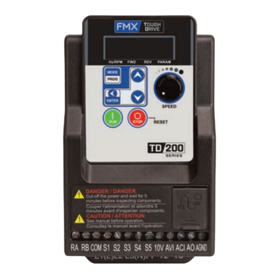
QUICK START
GUIDE
Applicable Models:
• 120V (1PH): 0.25 – 1HP
• 240V (1PH): 0.25 – 3HP
• 240V (3PH): 0.5 – 3HP
• 480V (3PH): 1 – 3HP
TD200-QS
CAUTION
Customer is solely responsible for validating application, operation,
maintenance, and code compliance and other information and data
relating to the installation, operation, safety, and maintenance of all
components. There is no guarantee that this information is suitable for
your application, nor is there any manufacturer/supplier assumption of
responsibility for your product design, installation, testing, or operation.
Information herein is provided "as is" with no guarantee of any kind. Every
attempt has been made to ensure the accuracy and reliability of the
information provided in this document.
NOTE
This document is intended to provide a short guide on the installation
and setup of a FMX Tough Drive. Refer to the user manual for all safety
precautions and further details regarding installing, wiring, operating,
servicing, or inspecting the AC Drive.
WARNING
Installation and wiring must be performed by qualified personnel
Do NOT remove any protective covers or attempt any wiring while input
power is applied. Connect all power wiring and control wiring before
applying input power. Always turn OFF the power supply before
attempting AC Drive installation and terminal wiring.
Internal capacitors hold a charge after power supply has been removed.
After disconnecting power, wait at least 10 minutes before touching any
wiring, circuit boards, or components.
Check all wiring to ensure all connections are correct after installation of
AC Drive and any other devices. Failure to comply could result in serious
injury, death, fire, or damage to the AC Drive.
Do not use an improper voltage source. Failure to comply could result in
in serious injury, death, fire, or damage to the AC Drive. Verify the rated
voltage of the AC Drive matches the voltage of the incoming power
supply before applying power.
Do not connect a contactor or switch in series with the AC Drive and the
motor.
STEP
1
Identify Drive Specifications
Check the label affixed to the side of the drive and make sure the
input and output power specifications match the available power
source and motor.
AC Drive Label
1
PRODUCT: E510-2P5-H-U
TD200-20P5-3PH
INPUT
: AC 3PH 200-240V (+10%,-15%) 50/60Hz 4A
OUTPUT : AC 3PH 0-599 Hz 2.6A
ENCLOSURE : IP20
5
P/N BARCODE
1
Verify receipt of proper drive model
2
Verify Input Power
3
Provide adequate circuit provision
• Ensure proper wire size
• Provide proper circuit protection
• Comply to all local codes and regulations
4
Output Amperage
• Ensure output is adequate to meet the full load amps of the
motor or application
5
Verify Environment
• Provide proper environmental protection
• Install drive in a clean and cool environment protected from
contaminants and debris
STEP
2
Mounting / Spacing Requirements
Minimum Spacing Requirements
Cooling Fan
Enclosure
4.8" / 12cm
2" / 5cm
4.8" / 12cm
Adequate thermal management is key to extending the life of the AC
drive. Overheating and excessive dust/debris will shorten the life of
the drive significantly.
-10°C - +50°C (14-122 °F)
Operating
If AC Drive is placed in an enclosure, provide
Temperature:
additional cooling and ventilation to maintain
ambient temperatures below 50°C (122 °F)
MOTOR RATING: 0.5 HP
IP20/NEMA 1
2
4
S/N BARCODE
Cooling Fan
Enclosure
2" / 5cm
2" / 5cm
Vent
Vent
Advertisement

Related Manuals for FMX TD200 Series


Summary of Contents for FMX TD200 Series
- Page 1 This document is intended to provide a short guide on the installation 4.8” / 12cm and setup of a FMX Tough Drive. Refer to the user manual for all safety precautions and further details regarding installing, wiring, operating, servicing, or inspecting the AC Drive.
- Page 2 STEP Wiring the AC Drive WARNING NOTE Depending on the AC drive model, terminal labels and layouts may be Circuit protection must be installed before AC drive. See section 2.3 slightly different. Please see table below for details on terminal labels of the user manual for the appropriate circuit breaker for your drive.
- Page 3 Commonly Used Parameters STEP Set Motor FLA I.D. Default Function Setting Range Refer to the motor nameplate for FLA (Amps) when setting up the 0: Keypad drive. For this example we will use a 460V motor rated at 1.5 Full 1: External Terminal (Control Main Run Command Load Amps.
- Page 4 STEP Set Main Command Source (Optional) Diagram 1: 2-Wire FWD/REV External Control (default) Example Procedure Forward FORWARD 1. Set using the steps below. Reverse 2. Press MODE/PROG. Display shows REVERSE 3. Use navigation keys to 2-Wire External Control Operation go to Terminal S1 Terminal S2...