Advertisement
Quick Links
P
Top
Wall
P
R
Top
HARDWARE LIST
(P) Anti-Tip Strap - 2pcs
(Q) M4 X 16MM - 2pcs
WARNING
Serious or fatal injuries can occur from
furniture tipping over. To prevent the furniture
from tipping over we recommend that it is
permanently fixed to the wall.
Wall fixing are not supplied with this product as different
wall material required different types of fixing devices.
Please make sure you use fixing suitable for the walls in
your home.
Q
Wall
S
Top
(R) M4 X 25MM - 2pcs
(S) PVC Wall Plug - 2pcs
CCO-TB117-WHT / PAGE 20
COCO SERIES
ASSEMBLY INSTRUCTION
CCO-TB117-WHT
IMPORTANT :-
PLEASE READ THESE INSTRUCTION CAREFULLY BEFORE STARTING ASSEMBLY.
*Please Keep For Future Reference Only.
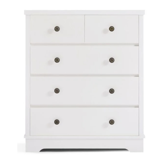
Dimensions
Width : 800mm
Depth : 400mm
Height : 945mm
TALLBOY
CCO-TB117-WHT / PAGE 1
Advertisement

Related Manuals for eliving FURNITURE COCO Series


Summary of Contents for eliving FURNITURE COCO Series
- Page 1 *Please Keep For Future Reference Only. COCO SERIES ASSEMBLY INSTRUCTION Wall Wall HARDWARE LIST (P) Anti-Tip Strap - 2pcs (R) M4 X 25MM - 2pcs (Q) M4 X 16MM - 2pcs (S) PVC Wall Plug - 2pcs Dimensions Width : 800mm...
-
Page 2: Hardware Needed
STEP 31 HARDWARE NEEDED: 2PCS 2PCS IMPORTANT TIPS AND MAINTENANCE iii)To avoid dulling, do not iv)Never use ammonia cleaning i)Keep children and animal away ii)Never put the liquid or damp place directly to the sunlight. product, because it will damage from working area because smaller on the furniture. - Page 3 STEP 29 HARDWARE NEEDED: 8PCS COMPONENTS :- Please check you have all the panels are listed below. PANELS 20&21 2x Drawer STEP 30 HARDWARE NEEDED: LAST THIRD 12PCS HOLE 4PCS THIRD HOLE PART LIST BACK LEG TOP PANEL 3pcs SIDE LEG_RIGHT LARGE DRAWER BACK 5pcs SIDE LEG_LEFT...
- Page 4 STEP 1 STEP 27 HARDWARE NEEDED: HARDWARE NEEDED: 12PCS 4PCS 10PCS 4PCS 4PCS 1,2,3,4 MAKE SURE THE ARROW ON THE CAM LOCK IS POINTING TOWARD THE HOLE ON THE EDGE OF THE PANEL. 1,2,3,4 2,3,4 FINISHED FRONT EDGE 2x Drawer STEP 2 STEP 28 FINISHED...
- Page 5 STEP 25 STEP 3 HARDWARE NEEDED: HARDWARE NEEDED: 6PCS 4PCS 3PCS 16PCS 3PCS 2PCS 4PCS Upper Second Hole MAKE SURE THE ARROW First Hole 3x Drawer ON THE CAM LOCK IS Last Third Hole SCREW MUST BE INSERTED POINTING TOWARD THE IN THE FIRST HOLE ON THE HOLE ON THE EDGE OF THE PANEL.
- Page 6 STEP 5 STEP 23 HARDWARE NEEDED: HARDWARE NEEDED: 4PCS 24PCS 16PCS 3PCS 2PCS 4PCS MAKE SURE THE ARROW ON THE CAM LOCK IS POINTING TOWARD THE HOLE ON THE EDGE OF THE PANEL. Upper Second Hole Last Third Hole First Hole 3x Drawer SCREW MUST BE INSERTED IN THE FIRST HOLE ON THE...
- Page 7 STEP 21 STEP 7 HARDWARE NEEDED: HARDWARE NEEDED: 6PCS 3PCS FRONT 8PCS 2PCS 2PCS BACK MAKE SURE THE ARROW ON THE CAM LOCK IS POINTING FINISHED TOWARD THE HOLE ON THE EDGE OF THE FRONT EDGE PANEL. Upper First Hole Upper Second Hole FINISHED FRONT...
- Page 8 STEP 9 STEP 19 HARDWARE NEEDED: 20PCS 10PCS MAKE SURE THE ARROW ON THE CAM LOCK IS POINTING TOWARD THE HOLE ON THE 6&7 EDGE OF THE PANEL. 14,15 14,15 STEP 10 STEP 20 HARDWARE NEEDED: 13PCS 16,20,21 ROUND EDGE CCO-TB117-WHT / PAGE 8 CCO-TB117-WHT / PAGE 13...
- Page 9 STEP 17 STEP 11 HARDWARE NEEDED: HARDWARE NEEDED: 8Sets 4PCS STEP 18 STEP 12 HARDWARE NEEDED: HARDWARE NEEDED: 6PCS 20PCS 13,19 CCO-TB117-WHT / PAGE 12 CCO-TB117-WHT / PAGE 9...
- Page 10 STEP 13 STEP 15 FINISHED FRONT EDGE STEP 14 STEP 16 HARDWARE NEEDED: CCO-TB117-WHT / PAGE 10 CCO-TB117-WHT / PAGE 11...
Need help?
Do you have a question about the COCO Series and is the answer not in the manual?
Questions and answers