
Subscribe to Our Youtube Channel
Related Manuals for BTI TC151

Summary of Contents for BTI TC151
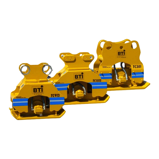
- Page 1 Revision : 05/2004 Manual # : 150-1010 OWNER’S MANUAL TC SERIES HYDRAULIC COMPACTORS For Models : TC51, TC71, TC80, TC91, TC151 & TC301...
-
Page 3: Table Of Contents
General ... TC51 Specifications ... TC71 Specifications ... TC80 Specifications ... TC91S Specifications ... TC151S / TC151SH Specifications ... TC301 / TC301H Specifications ... Hazard Alerts ... Sizing the Compactor ... Typical Hydraulic Circuits ... Installation ... Setting Flow & Pressure ... Start-Up ... -
Page 4: General
GENERAL BTI compactors are designed to mount on mini-excavators, backhoes and excavators. BTI compactors combine impulse force, down pressure, and vibration to work as soil compactors or pile/sheet drivers. The compactor has 3 basic components: • Mounting Bracket: attaches the compactor to the carrier boom and is complete with adjustable mounting pins. -
Page 5: Tc51 Specifications
Impulse Force: Oil Flow Req'd: Cycles/Minute: Hydraulic Connections: Minimum Tube I.D.: Operating Pressure: Base Plate Dimension: Compaction Area: Weight: Swivel Rotation: Locking Positions: Carrier Weight: Compactor Owner’s Manual TC51 SPECIFICATIONS TC51L/FC TC51H/FC 2,250 - 3,000 lb 2,250 - 3,000 lb 1,020 - 1,360 kg 1,020 - 1,360 kg 8 - 12 US gpm... -
Page 6: Tc71 Specifications
TC71S SPECIFICATIONS Impulse Force: Oil Flow Req'd: Cycles/Minute: Hydraulic Connections: Minimum Tube I.D.: Operating Pressure: Base Plate Dimension: Compaction Area: Weight: Swivel Rotation: Locking Positions: Carrier Weight: TC71S 3,300 - 5,000 lb 1,497 - 2,268 kg 13 - 17 US gpm 49 - 63 l/min 2,020 - 2,500 #12 JIC Male... -
Page 7: Tc80 Specifications
Impulse Force: Oil Flow Req'd: Cycles/Minute: Hydraulic Connections: Minimum Tube I.D.: Operating Pressure: Base Plate Dimension: Compaction Area: Weight: Swivel Rotation: Locking Positions: Carrier Weight: Compactor Owner’s Manual TC80 SPECIFICATIONS 5,000 - 8,200 lb 2,270 - 3,727 kg 20 - 26 US gpm 75 - 97 l/min 1,659 - 2,200 #12 JIC Male... -
Page 8: Tc91S Specifications
TC91S SPECIFICATIONS Impulse Force: Oil Flow Req'd: Cycles/Minute: Hydraulic Connections: Minimum Tube I.D.: Operating Pressure: Base Plate Dimension: Compaction Area: Weight: Swivel Rotation: Locking Positions: Carrier Weight: 5,000 - 8,200 lb 2,270 - 3,727 kg 20 - 26 US gpm 75 - 97 l/min 1,659 - 2,200 #12 JIC Male... -
Page 9: Tc151S / Tc151Sh Specifications
TC151S Impulse Force: 11,120 - 16,610 lb 5,055 - 7,550 kg Oil Flow Req'd: 25 - 31 US gpm 95 - 117 l/min Cycles/Minute: 1,800 - 2,200 Hydraulic Connections: #16 JIC Male Minimum Tube I.D.: 1" Operating Pressure: 1,500 - 2,000 psi 102 - 136 bar Base Plate Dimension: 28 x 36.5"... -
Page 10: Tc301 / Tc301H Specifications
TC301 / TC301H SPECIFICATIONS Impulse Force: Oil Flow Req'd: Cycles/Minute: Hydraulic Connections: Minimum Tube I.D.: Operating Pressure: Base Plate Dimension: Compaction Area: Weight: Carrier Weight: www.rockbreaker.com TC301 TC301H 16,300 - 24,300 lb 16,300 - 24,300 lb 7,409 - 11,000 kg 7,409 - 11,000 kg 35 - 43 US gpm 50 - 61 gpm... -
Page 11: Hazard Alerts
HAZARD ALERTS Danger, Warning, and Caution are hazard alerts used in this manual and on the compactor decals to identify hazards on or near the carrier and compactor. Danger - Immediate hazards, which WILL result in severe personal injury or death if the proper precautions are not taken. Warning - Hazards or unsafe practices, which COULD result in per- sonal injury or death if the proper precautions are not taken. - Page 12 HAZARD ALERTS Do not operate the compactor with personnel in the immediate area of the carrier and compactor. Note and avoid all hazards and obstructions such as overhangs, ledges, slide areas, electrical lines, underground cables, water mains, gas lines, etc. When operating close to electrical lines, underground cables, water mains or gas lines, contact the responsible authority and request assis- tance.
- Page 13 HAZARD ALERTS Hydraulic fluids are under high pressure. Fluid escaping under pressure can penetrate the skin causing serious injury. Relieve all pressure before disconnecting hoses. Do not use your hand to check for hydraulic leaks. If any fluid is injected into the skin, a doctor must surgically remove it within a few hours or gangrene may set in.
- Page 14 HAZARD ALERTS Head Foot Protection Protection Do not operate or service the compactor unless you are qualified. Avoid loose fitting clothing, loose or uncovered long hair, jewelry and loose personal articles. These can get caught in moving parts. Jewelry may also ground a live circuit. Know and use the protective equipment that is to be worn when operat- ing or servicing the carrier.
-
Page 15: Sizing The Compactor
The compactor must be sized properly for both the carrier on which it will be mounted and the work to be done. Sizing the Compactor based on the Type of Work Most applications require the soil under a road or load bearing surface to be compacted to 95% or greater than the density of the original material removed. - Page 16 SIZING THE COMPACTOR Always use a compactor sized to the carrier. A compactor that is too small for the carrier will damage the compactor, while a compactor too big will damage the carrier. Ensure you have the proper installation kit for attaching the compactor and that the carrier's hydraulic system meets the compactor flow and pressure requirements.
-
Page 17: Typical Hydraulic Circuits
To run, a compactor needs hydraulic flow in one direction within a work- ing pressure range. When installing the compactor the carrier hydraulic circuit must have the following: • The carrier must have a hydraulic circuit which will provide the correct flow •... - Page 18 TYPICAL HYDRAULIC CIRCUITS Carrier with Auxiliary Circuit Often a carrier is equipped with an auxiliary control valve (see Figure 1), this valve can be adjusted to provide the correct amount of oil flow to the compactor. A pressure relief cartridge can also be installed to protect the hydraulic components.
- Page 19 Carrier without Auxiliary Circuit If the carrier does not have an auxiliary control valve (see Figure 2), a priority flow control valve must be installed to direct oil flow from the normal circuit to the compactor. The priority flow control valve is usual- ly equipped with a flow adjustment and pressure relief.
-
Page 20: Installation
INSTALLATION There is no separate pressure adjustment on the compactor. The compactor's supply oil should be directed out the left side of the boom and the return line back on the boom's right side. A combination of hoses and steel tubing is recommended to keep the installation neat and cost effective. -
Page 21: Setting Flow & Pressure
For a compactor to operate properly it requires a specific oil flow and sufficient oil pressure. TC51L/FC: 1500-2200 psi @ 8-12 USgpm Oil Flow & Oil Pressure TC51H/FC: 1500-2200 psi @ 12-18 USgpm TC71: 1200-2000 psi @ 13-17 USgpm TC71FC: 1200-2000 psi @ 13-22 USgpm TC80 : 1300-2000 psi @ 20-26 USgpm TC91S: 1300-2000 psi @ 20-26 USgpm TC151S: 1500-2000 psi @ 25-31 USgpm... - Page 22 SETTING FLOW & PRESSURE Now adjust the oil flow on the carrier, so the flow meter reading equals: TC51L/FC: 8-12 USgpm (30-45 l/min) TC51H/FC: 12-18 gpm (44-68 l/min) TC71: 13-17 USgpm (49-63 l/min) TC71FC: 13-22 gpm (49-83 l/min) TC80: 20-26 USgpm (75-97 l/min) TC91S: 18-24 USgpm (68-91 l/min) TC151S: 25-31 USgpm (95-117 l/min) TC151SH: 35-43 gpm (132-163 l/min) TC301: 35-43 USgpm (132-163 l/min) TC301H: 50-61 gpm (189-231 l/min)
-
Page 23: Start-Up
START-UP Carrier oil should be clean and in accordance with the manufacturer's recommendations. After mounting the compactor on the boom and connecting the lines, bleed all air from the hydraulic system. Initially pump grease to the pins in the bracket until it oozes out around the pins. -
Page 24: Operation
OPERATION Compaction of Materials BTI compactors achieve material compaction by using impulse force and vibration to displace air and water pockets in the material. Compaction performance depends on 3 items: Use a short trial of the compactor to determine the optimum depth of lift and speed of boom travel to achieve the required density. - Page 25 Shut off the compactor and lift it into the air to a new position, or using minimum boom down-force slide the compactor along the ground. Avoid dragging the compactor's plate across the material surface ('ironing') while the motor is running. Forces exerted on the compactor by 'ironing' can cause premature failure.
- Page 26 OPERATION When compaction is complete, shut off compactor before lifting it from Shut-off Compactor the ground. Before Lifting Do not pound the ground with the compactor. Do not start in the middle of an un-compacted area. Always start at the edge, near a solid wall, bank, or a previously compacted area.
-
Page 27: Removal & Storage
Maintenance- Every 40 Hours of Operation Check hoses for wear and leaks, replace and tighten as required. The eccentric housing is filled with gear oil. This oil must be changed after the initial 50 hours. Then change oil every year. Use 80W90 gear oil. -
Page 28: Product Warranty
PRODUCT WARRANTY 1. BREAKER TECHNOLOGY Company (hereinafter referred to as BTI) war- rants this product against defects in materials and workmanship for a period of twelve (12) months from the date of installation. This warranty does not cover o-rings, seals, fittings, hoses, or other items considered normal wear items. These are covered by the Limited Warranty period of thirty (30) days. -
Page 29: Bracket Options
Bolt-On QA Non-Swivel Top Mount: Available as an option on the TC71 & TC80 Compactor Owner’s Manual BRACKET OPTIONS Bolt-On Rigid Top Mount: (Shown on TC80) Standard equipment on TC51, TC71, TC80 & TC301 QA Swivel Top Mount: Standard equipment on TC91S & TC151S. -
Page 30: Tc51 Parts
TC51 PARTS When ordering give Part Number, Part Name, Model and Serial #. www.rockbreaker.com... - Page 31 1008453 Retaining Ring 650-8796 Bearing Housing 1800288 Fitting 1009488 Hydraulic Motor 1912007 Bolt - Grade 8 1001856 Nordlock Washer Set 1008798 Gasket 1911113 Bolt - Grade 5 1001856 Nordlock Washer Set 1912270 Button Head Cap Screw 1941002 Flat Washer 1009487...
-
Page 32: Tc71 Parts
TC71 PARTS When ordering give Part Number, Part Name, Model and Serial #. www.rockbreaker.com... - Page 33 Eccentric Assembly 1008936 Bearing 1008935 Reatining Ring 1800849 O-Ring 220-2707 Bearing Housing - Motor Side 1912009 Bolt - Grade 8 1001856 Nordlock Washer Set 1008798 Gasket 1801470 Plug 1800288 Fitting 1009505 Hydraulic Motor 1912128 Bolt - Grade 8 1001857 Nordlock Washer Set...
-
Page 34: Tc80 Parts
TC80 PARTS When ordering give Part Number, Part Name, Model and Serial #. www.rockbreaker.com... - Page 35 For Mounting Bracket options and parts information contact BTI. Part Number Description Top Mount 370-0007 Top Frame Weldment 1008925 Isolator 1912261 Bolt 1941004 Washer 1932014 Locknut H409-KKK-021 Hose Assembly 1800289 Fitting 650-8641 Stud 1009833 Motor 1912020 Hex Head Bolt 1801983...
-
Page 36: Tc91S Parts
TC91S PARTS When ordering give Part Number, Part Name, Model and Serial #. www.rockbreaker.com... - Page 37 650-8501 Top Mount Weldment 1001536 Bottom Bearing Washer 1001857 Nordlock Washer Set M12 1912020 Bolt 1/2” -13UNC x 1 1/2” LG GR8 Pin - Contact BTI for Part # 1002184 Quick Pin c/w Chain 650-8296 Clevis Pin 650-8617 Frame Weldment...
-
Page 38: Tc151S Parts
TC151S PARTS When ordering give Part Number, Part Name, Model and Serial #. www.rockbreaker.com... - Page 39 650-8587 Frame Weldment 1800419 Fitting 1800262 Fitting 1001529 Quick Pin 1801223 Fitting 1912086 Bolt 3/4” NC x 3”LG GR.8 1912138 Bolt 5/8” NC x 1 1/2” GR.8 1001768 Nordlock Washer Set 650-8592 Bearing Housing 1801020 Pipe Plug 1801980 O-Ring 1002182...
-
Page 40: Tc151Sh Parts
TC151SH PARTS www.rockbreaker.com... - Page 41 650-8587 Frame Weldment 1800419 Fitting 1800262 Fitting 1001529 Quick Pin 1801223 Fitting 1912086 Bolt 3/4” NC x 3”LG GR.8 1912138 Bolt 5/8” NC x 1 1/2” GR.8 1001768 Nordlock Washer Set 650-8592 Bearing Housing 1801020 Pipe Plug 1801980 O-Ring 1002182...
-
Page 42: Tc301 Parts
TC301 PARTS When ordering give Part Number, Part Name, Model and Serial #. www.rockbreaker.com... - Page 43 BTI. Part Number Description 390-0002 Top Weldment 1800262 Fitting 1800419 Fitting 1001858 Nordlock Washer Set M20 1912046 Bolt 3/4” -10UNC x 2 1/2” GR.8 650-8526 Bearing Housing 1801020 Pipe Plug 1801855 O-Ring 1006886 Spherical Roller Bearing 1006919...
-
Page 44: Tc301H Parts
TC301H PARTS www.rockbreaker.com... - Page 45 BTI. Part Number Description 650-8680 Top Weldment 1801591 Fitting 1800420 Fitting 1001858 Nordlock Washer Set M20 1912046 Bolt 3/4” -10UNC x 2 1/2” GR.8 650-8526 Bearing Housing 1801020 Pipe Plug 1801855 O-Ring 1006886 Spherical Roller Bearing 1006919...
- Page 48 SOLON FACILITY RIVERSIDE FACILITY 30625 Solon Industrial Drive, 3464 DURAHART ST. SOLON OHIO, RIVERSIDE,CALIF. 44139 U.S.A. 92507 U.S.A. PH. 440-542-3720 PH. 909-369-0878 FAX. 440-542-3721 FAX. 909-369-8281 THORNBURY FACILITY 35 ELGIN ST., THORNBURY,ONT. N0H 2P0 CANADA PH. 519-599-2015 FAX. 519-599-6803...
Need help?
Do you have a question about the TC151 and is the answer not in the manual?
Questions and answers