Advertisement
Quick Links
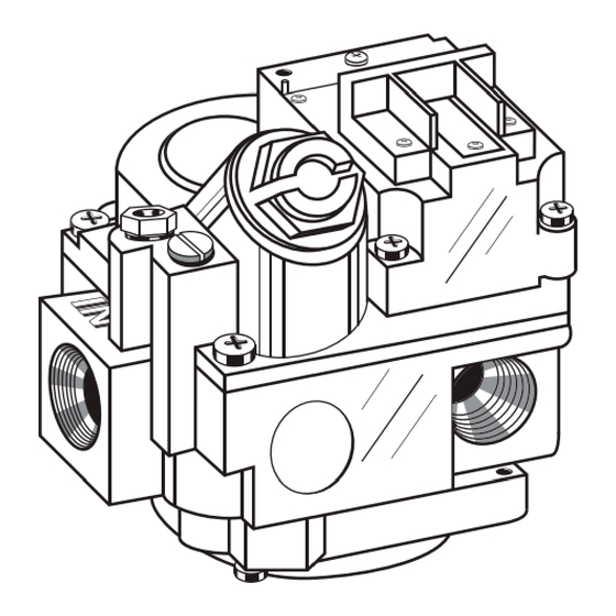
The Robertshaw® 700 Series Gas Controls are designed for a wide variety of
heating applications. Models are available for: Manual, Millivolt, Hydraulic,
24 Volt and Line Voltage. Models are available with and without a pressure
regulator. A field-addable pressure regulator is available separately. (NOTE:
The pressure regulator is "built-in" on hydraulic models and requires
replacement of the operator assembly when converting from one gas to
another. Controls are multiposition and can be mounted in any position
(except upside-down).
SPECIFICATIONS
ELECTRICAL RATINGS
24 Volt Models
Millivolt Models
Line Voltage Models
CONTROL VOLTAGE IDENTIFICATION - WIRING BLOCK
PRESSURE REGULATOR (Optional by Model)
Natural Gas
L.P. Gas
TEMP. RANGE (Hydraulic Models Only)
DIAL EQUIVALENTS (Hydraulic Models Only)
Standard Dial Type
Dial Position
1
2
Temperature oF
58o
62o
Remote Dial Type
Dial Position
Low
Temperature oF
50o
CAPILLARY LENGTH (Hydraulic Models Only)
Single capillary type
Remote dial type
BULB O.D. & LENGTH (Hydraulic Models Only)
PILOT OUTLET
AMBIENT TEMPERATURE
MAXIMUM INLET PRESSURE
INSTALLATION INSTRUCTIONS
Turn off gas supply and electrical power to equipment before servicing.
PIPING
1. Check replacement valve for multiple outlets (side outlets). If it has
them, be sure all unused outlets are plugged using the socket plugs
provided.
2. Pipe or tubing must be clean and free of scale and dirt.
3. Make sure gas piping is pressure tested before control is connected.
High pressure can damage control causing a hazardous condition.
Do not subject control to more than 1/2 psi, (14" W.C.) inlet pressure.
4. If it is not already installed, a drip leg (sediment trap) must be added to
the gas supply line to control. (See figure to the right.) All piping must
comply with local codes and ordinances and with National Fuel Gas Code
(ANSI Z223.1/NFPA, No. 54).
5. Using pipe thread compound or tape (suitable for gas), apply a small
amount on the male pipe threads. Leave the first two threads clean.
12 VDC - 0.18 amps
24 VDC - 0.2 amps
250 MV to 750 MV
120 VAC - .034 amps
240 VAC - .017 amps
Factory set at 3.5" W.C.
Factory set at 11.0" W.C.
3
4
5
6
7
66o
70o
74o
78o
82o
Med.
70o
Combination 18" and 48"
-40° to 175°F
14" W.C. (1/2 PSI)
GAS HEATING CONTROLS
8
HI
86o
90o
High
90o
36"
THIS DEVICE SHOULD BE INSTALLED BY A QUALIFIED TECHNICIAN
1/4" x 8"
WITH DUE REGARD FOR SAFETY AS IMPROPER INSTALLATION
1/4" Tubing
COULD RESULT IN A HAZARDOUS CONDITION.
Never use compound on female threads as it might be pushed into the
control body.
6. The gas valve is multiposition and can be mounted in any position
(except upside down) without effecting its operation.
7. Install gas valve so gas flow conforms with the inlet and outlet of the control.
1
INSTALLATION DATA
700 SERIES
CAUTION
Advertisement

Related Manuals for Robertshaw 700 Series

Summary of Contents for Robertshaw 700 Series
- Page 1 700 SERIES GAS HEATING CONTROLS The Robertshaw® 700 Series Gas Controls are designed for a wide variety of heating applications. Models are available for: Manual, Millivolt, Hydraulic, 24 Volt and Line Voltage. Models are available with and without a pressure regulator.
- Page 2 3/16” adaptor terminal that is included with this gas valve. thermocouple or magnet and is unnecessary. The 700 Series millivolt valves are designed to operate with 1950 and 1951 HYDRAULIC MODELS Series Thermopiles. These valves will also operate with any competitive thermopiles having outputs of 250MV to 750MV.
- Page 3 OPERATING INSTRUCTIONS 4. Follow standard lighting procedure. 5. Check closed circuit thermocouple output, if less that eight millivolts, WARNING replace with 1970 or 1980 thermocouple. To avoid possible injury, fire and explosion, please read and follow these 6. Repeat standard lighting procedure after thermocouple replacement. precautions and all instruction on appliance before lighting the pilot.
- Page 4 Hydraulic models do not have a replaceable pressure regulator. If it is necessary to change to another gas then the valve operator will need to be changed. 191 E. North Avenue Robertshaw®, Ranco®, Paragon® and Uni-Line® are www.uni-line.com Carol Stream Illinois 60188 USA For Technical Service trademarks of Robertshaw its subsidiaries and/or www.robertshaw.com...
Need help?
Do you have a question about the 700 Series and is the answer not in the manual?
Questions and answers