
Related Manuals for Weishaupt WRSol 1.0


Summary of Contents for Weishaupt WRSol 1.0
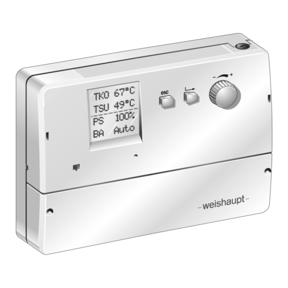
- Page 1 Installation and operating instructions Solar controller WRSol 1.0 83258202 - 1/2008...
- Page 2 Conformity Certification to ISO/IEC Guide 22 4800000001 Max Weishaupt GmbH Manufacturer: Max-Weishaupt-Straße Address: D-88475 Schwendi Product: Solar controller WRSol 1.0 WRSol 2.0 The product described above conforms to: DIN EN 60730-1, -2-9 Document No. DIN EN 61000-6-1, -6-3 In accordance with the directives...
-
Page 3: Table Of Contents
Contents 1 Safety instructions 2 About the Weishaupt solar controller WRSol 1.0 2.1 What does the solar controller do 2.2 What you have to observe 3 Installation and connection 3.1 Included in delivery 3.2 Wall mounted installation 3.3 Commissioning 3.4 Electrical connection 4 Hydraulic variations 4.1 Variation 1... - Page 4 8 What to do if…? 8.1 Fault messages (fault display) 8.2 Displays 8.3 Cause and rectification of faults 9 Technical data 9.1 Electrical data 9.2 Permissible ambient conditions 9.3 Dimensions 9.4 Temperature sensor data 9.4.1 Sensor characteristics Appendix Check list Commissioning log of adjustable parameters ‘Change settings’...
-
Page 5: Safety Instructions
Guarantee and liability • in compliance with all the information in the Weishaupt will not accept liability or meet any guarantee installation and operating instructions claims for personal injury or damage to property arising as a result of one or more of the causes below: Faults, which could affect the safe operation, should be •... -
Page 6: About The Weishaupt Solar Controller Wrsol
About the Weishaupt solar controller WRSol 1.0 The Weishaupt solar controller (WRSol ) allows Easy operation easy control of your solar system. Three levels are available to you: Some characteristics of the WRSol: • The standard display, in which up to three selected •... -
Page 7: Installation And Connection
Immersion sensor STF 222.2 sensors. (2.5 m, grey cable, -w- No. 660 228) • Operating instructions WRSol 1.0 3.2 Wall mounted installation Note: Screw in the top screw only so far that it is still possible to hook in the controller. -
Page 8: Commissioning
3.3 Commissioning The WRSol 1.0 is constructed in such a way, that the function of the controller and the type of setting parameters can be set by selecting the relevant hydraulic variation. Only the selection menus and setting parameters required for the hydraulic variation selected will then be displayed. -
Page 9: Electrical Connection
3.4 Electrical connection Terminal rail left (sensor) Terminal rail right (outputs / voltage supply) Connection Improper installation or repair attempts can Remove terminal rail cover. cause life-threatening conditions through Connect electric shock. The installation must only be • sensor lines, carried out by an electrician with the relevant DANGER •... - Page 10 Wiring diagram WRSol 1.0 WRSol 1.0 3,15A (–) ϑ ϑ TSU/ TKO/ TSB/ TFK/ PFK/ TPU/ L N PE 230V 1/N/PE 50Hz Protective earthing (Null Potential Difference) to local regulations Legend Note: The output 1 (PS, PFK and VRA) must have a TFK Temperature sensor solid fuel boiler max.
-
Page 11: Hydraulic Variations
ATTENTION 4.1 Variation 1 Storage tank with collector and back-up heating influence The WRSol 1.0 determines the temperature differential between the collector sensor (TKO) and the reference sensor (TSU). As soon as the temperature differential is greater than the value set ( S S t t o o r r a a g g e e D D i i f f f f . . O O n n ), the solar pump is switched on and the tank is topped up, until the switch off condition ( S S t t o o r r a a g g e e D D i i f f f f . -
Page 12: Variation 20
4.3 Variation 15 Return temperature increase The WRSol 1.0 determines the temperature differential between the calorifier sensor (TPO) and the return flow sensor (THR). As soon as the temperature differential is greater than the value set ( R R e e t t u u r r n n f f l l o o w w D D i i f f f f . . O O n n ), the three way valve (VRA) is activated (AB–B) and the available energy from... - Page 13 4.5 Variation 48 Storage tank supply by solid fuel burner The WRSol 1.0 compares the solid fuel boiler temperature (TKF) with the reference sensor (TPU). If the temperature differential determined is greater than the value set ( S S o o l l i i d d f f u u e e l l . . D D i i f f f f . . O O n n ) the pump is switched on, if the default minimum temperature ( S S o o l l i i d d f f u u e e l l .
-
Page 14: Operation
Operation 5.1 Display and operating elements LCD display Enter button Pressing this button confirms entries and changes. Dial knob Escape button Return to the main display. This key is used to exit settings. Any unsaved entries will be lost. Return by one level at a time. -
Page 15: Where Do I Find What
5.3 Where do I find what… Standard display By pressing the key in the standard menu the following selection menus can be accessed. 67°C By pressing the key you can return to the base menu. 49°C 100% Auto Selection menu Sub menu Auto Select... -
Page 16: Collect. Temp. Minimum 20°C
Hydraulic variations Collect. temp. minimum PS speed minimum Volume flow Heat capacity Frost protection Tank diff. ON Calorifier diff. ON Swim pool diff. ON Return diff. ON Tank diff. OFF Calorifier diff. OFF Change Swim pool diff. OFF settings Swim pool Control Diff. Return diff. - Page 17 SolarPump PS Check Solid fuel pump Heating return increase or accept Multi funct. output output Collector protection Note Select This parameter has to Start optim. collector be reselected when Swim pool loading options changing variation. Set factory setting Fault codes Display Delete fault codes faults...
-
Page 18: Display
5.4 Display Standard value Changing the standard display The standard display is recognised by its 4 lines with a dotted line in the centre of the display. 67°C 49°C In the first three lines of the display, three temperatures, values or switch conditions of the outputs are displayed. 49°C 100% The fourth line contains the operation selection switch. - Page 19 Selection menu Selection menu A selection menu only has text and no dotted line. The sub menu is reached by pressing the , pressing means exit, any changes not saved are lost. Select temp. + values Sub menu Sub menu A sub menu has a dotted line in the centre of the display.
-
Page 20: Parameters
Parameters 6.1 Select type of operation Auto Select Manual type of operation Use: The function of the solar controller can be stipulated using selection menu point S S e e l l e e c c t t t t y y p p e e o o f f o o p p e e r r a a t t i i o o n n . A A u u t t o o Automatic operation to the criteria set. -
Page 21: Select Temperature And Values
6.2 Select temperatures and values Collect. temp. act. value Select temp. + values Version Use: Note: The values, which will be displayed or hidden in the menu, depend on the H H y y d d r r a a u u l l i i c c In this selection menu, temperatures and values can be selected and taken over for the standard display v v a a r r i i a a t t i i o o n n currently set under C C h h a a n n g g e e... - Page 22 Select temperatures and values continued Value indicator which shows the Reset : Automatic after internal 24 hour countdown and Collect. highest daily collector temperature. when pressing reset. temp. maximum Variation: 1, 12, 20 120.8°C Current rating of collector in kW Rating current collect.
-
Page 23: Change Settings
6.3 Change setting Hydraulic variation Change setting Multi funct. output Use: Note: Only the settings stored for the hydraulic This selection menu is used to carry out site specific variation selected are displayed in the menu. settings (preferably by a heating engineer). Settings without function in the selected variation are not shown. - Page 24 Change setting continued Temperature differential between Setting range: 0 K…40 K Tank collector sensor (TKO) and storage tank sensor (TSU) as switch on criteria for Presetting: 7.0 K Diff. the solar pump. 7.0K Variation: 1 Temperature differential between Setting range: 0 K…40 K Calorifier collector sensor (TKO) and calorifier...
-
Page 25: Tank Temp. Setpoint
Change setting continued Temperature differential between Setting range: 0 K…40 K Return return sensor (THR) and calorifier sensor “top” (TPO), at which the Presetting: 2.0 K Diff. three way valve (VRA) is de-energised. Variation: 15 2.0K Release level for external heating Setting range: 0°C…70°C Tank... -
Page 26: Tank Temp. Maximum
Change setting continued Maximum achievable tank temperature. Setting range: 20°C…95°C Tank The solar pump is switched off once this temperature is reached, if the passive Presetting: 90°C Temp. collector protection is switched off Maximum (setting collector protection: 0, 2 or 4). Depending on the hardness of the hot water it may be necessary to reduce the temperature to prevent excessive 90.0°C... -
Page 27: Psolidf. Speed Minimum
Change setting continued Lower limit value of modulation Setting range: 10%…100% PSolid f. range of feeder pump. Presetting: speed Minimum Variation: 48 If the temperature at collector sensor Variation: 1, 12, 20 Collector (TKO) increases by this value or more and if the option “Start optimisation Setting range: 0.0…10K/Min. -
Page 28: Test Outputs
6.4 Test outputs SolarPump PS Test or Solid f. pump Heating return increase take over Multi-funct. output outputs Note: As long as the display is flashing, the value has Here, you can check the current switch condition of the not been taken over and will revert to the outputs. -
Page 29: Select Options
6.5 Select options Collector protection Select Start optim. collect. Swim pool loading options Set factory presetting Use: Note: If the hydraulic variation is changed, parameter Overheat protection has to be Independent of the hydraulic variation used, additional function and be activated or blocked (only by a heating re-selected. -
Page 30: Display Faults
6.6 Display faults Fault codes Display Delete fault codes faults Use: Here, a fault which has occurred can be called up as a number code. The faults listed in Chapter 8 reset automatically once the cause has been rectified. One exception is fault 1, this remains saved within the controller and can only be reset using D D e e l l e e t t e e f f a a u u l l t t c c o o d d e e s s . -
Page 31: Functions
Functions 7.1 Collector protection In addition to the basic function of the controller it is 2. Active protection: possible to further protect the system against overheating The following two active protection functions are via a passive and or active protection function. In the basic possible: function (setting 0) the solar pump is switched off if the “Tank Temp. -
Page 32: Energy Management Via The Mfa Output
7.2 Energy management via the MFA output The multi-function output (potential free contact, terminal 5/6) must be selected site specific. With storage tank operation (DHW), reference sensor With calorifier operation, reference sensor TPU With good solar yield (a a v v e e r r a a g g e e r r a a t t i i n n g g P P S S above •... -
Page 33: Pump Standby Protection
7.4 Pump standby protection To avoid seizing of the actuators fitted, output terminal X1:1 is activated for approx. 35 seconds every 24 hours. 7.5 Reference value of pump speed control in conjunction with collectors The controller is equipped with speed control which is Reference value for the speed control: used to drive the pump via direct drive shaft. -
Page 34: Pump Control In Conjunction With A Solid Fuel Boiler
7.6 Pump control in conjunction with a solid fuel boiler The controller is equipped with speed control which drives the pump by direct drive shaft. Switch on conditions 1.) The solid fuel boiler must have reached its minimum temperature. SolidF temp. actual value ≥ SolidF temp. minimum 2.) If the boiler temperature reaches the calorifier Note: temperature (TPU) plus the S S o o l l i i d d F F d d i i f f f f . -
Page 35: Solid Fuel Boiler Functions
7.7 Solid fuel boiler functions The solar controller has three different solid fuel boiler functions. 1. Solid fuel boiler minimum temperature To release solid fuel boiler operation, this Example: SolidF.temp. minimum = 30°C temperature must be exceeded. The limit value SolidF. -
Page 36: Manual Operation
Heat capacity at 50°C: This solar controller contains a function for calculating the energy yield on the basis of the temperature differential -weishaupt- Solar thermal fluid 3.73 kJ/lK between the collector temperature (TKO) and the Tyfocor L (45% Propylene Glycol) reference sensor (TSU, TPU, TSB) via the throughput quantity (volume flow). -
Page 37: What To Do If
What to do if ...? 8.1 Fault messages (fault display) The faults recognised by the controller Fault are displayed with a fault code and can be assigned or rectified here. codes The fault code display is reset by Delete confirming with Yes. fault codes Code... -
Page 38: Displays
Code Description Cause Rectification Solid fuel boiler sensor bottom TFK has Sensor or cable Check installation, if necessary short or open circuit short or open circuit replace sensor Note: The solid fuel pump is driven at maximum speed (100%). Once the cause of the fault has been rectified, the fault message is automatically reset. The calorifier sensor top TPO has Sensor or cable Check installation, if necessary... -
Page 39: Technical Data
Technical data 9.1 Electrical data Mains voltage__________________________230 V ± 10% Micro fuse 3.15 A slow Mains frequency __________________________ 50-60 Hz Consumption ________________________________7 VA Voltage meas. circuit ______________12 V, insulated 4 KV Breaking capacity outputs: Electronic outputs ______________~230 V, 1 A, 50 Hz Minimum current ______________________20-40 mA Mechanical outputs __________~230 V, 6 (2) A, 50 Hz External unit fuse ______________________________16 A... -
Page 40: Temperature Sensor Data
9.4 Temperature sensor data Sensor element NTC 5000 Ω at 25°C Sensor Measuring Measurement Ambient Cable Cable Order range accuracy temperature material length number Immersion sensor STF 225 -10…240°C 0…70°C ± 0.5K -50…250°C Silicone (blue) 660 229 Immersion sensor STF 222.2 -10…130°C 0…50°C ±... -
Page 41: Sensor Characteristics
9.4.1 Sensor characteristics Sensor characteristic curve (Resistance values without self-heating) The Weishaupt controller system offers the possibility of displaying the correct connection of all sensors and the respectively measured temperature. To check the sensors and simulation of relevant sensor temperatures, value pairs for all units used (sensor temperature/resistance value) are listed in the following table. -
Page 42: Appendix
Appendix Contents • Checklist • Commissioning log Checklist Carry out wiring of controller to the variation selected. Supply connection made to wiring schematic (only with Emergency/Off switch and pre-fusing). Are the sensors connected displayed. Check plausibility of temperatures and values. Is the pump driven (pos. - Page 43 Commissioning log of adjustable parameters ‘Change settings’ (please complete) Parameter Setting range Presetting Set to Hydraulic variation Variation 1, 12, 15, 20, 48 [________] Collect. temp. minimum 0°C…70°C 20°C [________] PS Speed minimum 10%…100% [________] Volume flow 0.1 l/m…500.0 l/m 1.5 l/m [________] Heat capacity...
-
Page 44: Commissioning Log Of Adjustable Parameters 'Options' (Please Complete)
Commissioning log of adjustable parameters ‘Options’ (please complete) Parameter Setting range Presetting Set to Collector protection 0 ... 5 [________] Start optimisation collect. yes / no [________] Swim pool loading yes / no [________] Set factory presetting yes / no [________]... - Page 45 Notes...
- Page 46 Control technology / From control panels to complete building management building systems – at Weishaupt you can find the entire management spectrum of modern control technology. Future oriented, economical and flexible.