Table of Contents
Advertisement
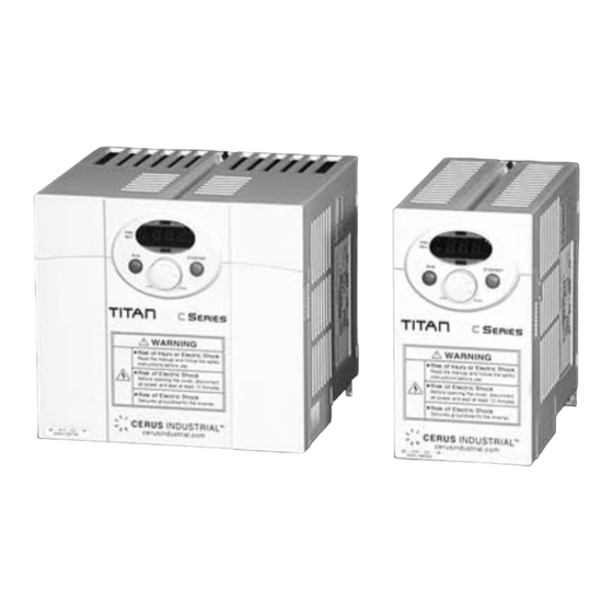
C Series
Micro 1Ø Input Sensorless Vector Inverter
Constant Torque
Sensorless/Space Vector Control
0.5 to 3HP, 200-230VAC
1Ø input, 3Ø output
Installation, Operation, &
Maintenance Manual
As with all electrical products, read manual
thoroughly before operating. Only qualified, expert
personnel should perform maintenance and
installation.Contact the nearest authorized service
facility for examination, repair, or adjustment. Do
not disassemble or repair unit; death or injury to
electrical shock or fire hazard may result.
Product improvement is a continual process at
Cerus Industrial. Specifications and manual data
subject to change. Consult factor for additional
information.
CAUTION, SAFETY WARNING
�����
����������
��� ������ ������ ��� ����� ��������
���� ����� ������������
�������� ������������
�
Advertisement
Table of Contents

Summary of Contents for Cerus Industrial C Series
- Page 1 Micro 1Ø Input Sensorless Vector Inverter Constant Torque Sensorless/Space Vector Control 0.5 to 3HP, 200-230VAC 1Ø input, 3Ø output Installation, Operation, & Maintenance Manual As with all electrical products, read manual thoroughly before operating. Only qualified, expert personnel should perform maintenance and installation.Contact the nearest authorized service facility for examination, repair, or adjustment.
-
Page 2: Safety Instructions
Particular attention should be directed because dangerous voltage may be present. Keep operating instructions handy for quick reference. Read this manual carefully to maximize the performance of C series inverter and ensure its safe use. Do not remove the cover while power is applied or the unit is in operation. -
Page 3: Operating Precautions
Do not install the drive on a flammable surface. Do not place flammable material nearby the drive. Otherwise, fire could occur. Remove the input power from the drive if a hardware failure occurs. Otherwise, it could result in a secondary accident and fire. The drive surface can emit high temperature. - Page 4 (2) Wiring Do not connect a power factor correction capacitor, surge suppressor, or RFI filter to the output of the inverter. The connection orientation of the output cables U, V, W to the motor will affect the direction of rotation of the motor. Incorrect terminal wiring could result in the equipment damage.
- Page 5 The purpose of this manual is to provide the user with the necessary information to install, program, start up and to maintain the C series inverter. To assure successful installation and operation, the material presented on this manual must be thoroughly read and understood before proceeding.
-
Page 6: Table Of Contents
Safety Instructions Basic information and precautions Important precautions Product Details Removal and reinstallation Installation Installation precautions Dimensions Wiring Terminal wiring Specifications for power terminal block wiring I/O terminal block specification PNP/NPN selection and connector for communication option Basic configuration Connection of peripheral devices to the inverter Recommended MCCB, Earth leakage circuit breaker (ELB) and Magnetic contactor specification Recommendable AC/DC Reactor... - Page 7 Basic operation Frequency Setting and Basic Operation Function list Drive Group Function Group 2 Function Group 2 I/O Group Control block diagram Frequency and Drive mode setting Accel/Decel setting and V/F control Basic Functions Frequency mode Multi-Step frequency setting Run Command setting Accel/Decel time and unit setting V/F control Stop mode select...
- Page 8 11. Monitoring 11.1 Operating status monitoring 11.2 Monitoring the I/O terminal 11.3 Monitoring fault condition 11.4 Analog Output 11.5 Multi-function output terminal (MO) and Relay (30AC) 12. Protective functions 12.1 Electronic Thermal 12.2 Overload Warning and trip 12.3 Stall prevention 12.4 Output phase loss protection 12.5 External trip signal 12.6 Inverter Overload...
-
Page 9: Basic Information And Precautions
(Refer to Wiring section 3-1). Chapter 1. Basic information & precautions Motor rating 0.4 [kW] 0.75 [kW] 1.5 [kW] 2.2 [kW] Inverter Type Input power Rating Output Power Rating Inverter Capacity (HP) Bar Code Serial Number Series Name Single Phase C series inverter (200V) -
Page 10: Product Details
1.2 Product Details 1.2.1 Appearance Status LED Display Window Front Cover: Remove when wiring and changing parameter setting. Bottom Cover: Remove when wiring input power and motor. 1.2.2 View without the front cover Refer to section 1-3 for front cover removal. RUN Button NPN/PNP Select Switch... -
Page 11: Removal And Reinstallation
1.3 Removal and reinstallation 1.3.1 Removal of the front cover To change parameter setting: Press the pattern with a finger slightly as 1) and push it downward as 2). Then 4-way button will appear. Use this button for parameter setting and changing the value. Removal for wiring: The method is the same as shown in 1. - Page 12 Removal for wiring input power and terminals: After removing the front cover, lift the bottom cover up to disconnect. To access control terminals: after finishing power terminal wiring, reinstall the bottom cover and then start wiring control terminals. Note : Use the recommended size of the cable as indicated in this manual ONLY. Using larger size cable may lead to mis-wiring or damage the insulation.
-
Page 13: Installation
2.1 Installation precautions Handle the inverter with care to prevent damage to the plastic components. Do not hold the inverter by the front cover. It may fall off. Install the inverter in a place where it is immune to vibration (5.9 m/s The inverter is under great influence of ambient temperature Install in a location where temperature is within the permissible range (14~122°F/-10~50°C). - Page 14 When two or more inverters are installed or a ventilation fan is mounted in inverter panel, the inverters and ventilation fan must be installed in proper positions with extreme care taken to keep the ambient temperature of the inverters below the permissible value. If they are installed in improper positions, the ambient temperature of the inverters will rise and ventilation effect will be reduced.
-
Page 15: Dimensions
2.2 Dimensions 0.4, 0.75 kW (1/2~1 HP) Dimension CI-000-C2-1P 79 (3.11) 143(5.63) 143(5.63) Weight 0.95(2.09) Kg (lbs) mm (inch) CI-001-C2-1P CI-002-C2-1P 79 (3.11) 156(6.14) 143(5.63) 143(5.63) 143(5.63) 143(5.63) 0.97(2.14) 1.94(4.28) Chapter 2. Installation CI-003-C2-1P 156(6.14) 143(5.63) 143(5.63) 2(4.41) - Page 16 1.5, 2.2 kW (2~3HP) Dimension CI-000-C2-1P 79 (3.11) 143(5.63) 143(5.63) Weight 0.95(2.09) Kg (lbs) mm (inch) CI-001-C2-1P CI-002-C2-1P 79 (3.11) 156(6.14) 143(5.63) 143(5.63) 143(5.63) 143(5.63) 0.97(2.14) 1.94(4.28) Chapter 2. Installation CI-003-C2-1P 156(6.14) 143(5.63) 143(5.63) 2(4.41)
-
Page 17: Wiring
3. Wiring 3.1 Terminal wiring Single phase AC input 200V ~ 230V Common Motor Termi- EXTG AC line voltage input Terminal Inverter DC P/S Terminal CLASS B motor EMI FILTER (Option) Earth Ground Chapter 3. Wiring P4 P5 VR V1 CM I AM 30A 30B 30C MO EXTG P24 P1 P2 CM P3 Features... -
Page 18: Specifications For Power Terminal Block Wiring
3.2 Specifications for power terminal block wiring CI-000-C2-1P Input wire size Output wire Ground Wire ,3.5 φ Terminal Lug Tightening 13kgf cm Torque Make sure the input power is off before wiring. When power supply is switched off following operation, wait at least 10 minutes after LED keypad display is off before you start working on it. - Page 19 Use the Type 3 grounding method (Ground impedance: Below 100ohm). Use the dedicated ground terminal to ground the inverter. Do not use the screw in the case or chassis, etc. for grounding. Dedicated Ground Terminal Note: Remove front and bottom cover before starting grounding. Caution: Follow the specifications below when grounding the inverter.
-
Page 20: I/O Terminal Block Specification
3.3 I/O terminal block specification Terminal Terminal Description P1/P2/P3 Multi-function input T/M P1-P5 P4/P5 Common Terminal for P1-P5, AM, P24 12V power supply for external potentiometer 0-10V Analog Voltage input 0-20mA Analog Current input Multi-function Analog output Multi-function open collector output T/M EXTG Ground T/M for MO... -
Page 21: Pnp/Npn Selection And Connector For Communication Option
2. Communication Option Card Connector: Install Communication option card here. Note: MODBUS RTU option card is available for C series. Refer to C series MODBUS RTU option manual for more details. 1. When using P24 [NPN] 2. When using 24V... - Page 22 Chapter 3. Wiring Notes:...
-
Page 23: Basic Configuration
Connection of peripheral devices to the inverter The following devices are required to operate the inverter. Proper peripheral devices must be selected and correct connections made to ensure proper operation. An incorrectly applied or installed inverter can result in system malfunction or reduction in product life as well as component damage. You must read and understand this manual thoroughly before proceeding. -
Page 24: Recommended Mccb, Earth Leakage Circuit Breaker (Elb) And Magnetic Contactor Specification
CI-002-C2-1P CRS33b, EBS333 CI-003-C2-1P CRS33b, EBS333 Recommendable AC/DC Reactor Model AC input fuse CI-000-C2-1P CI-001-C2-1P CI-002-C2-1P CI-003-C2-1P MCCB/ Magnetic ELB(LG) Contactor AC reactor 2.13mH, 5.7A 1.20mH, 10A 0.88mH, 14A 0.56mH, 20A Chapter 4 Basic configuration Note CRC-12 CRC-18 CRC-25 CRC-32 DC reactor 7.00mH, 5.4A... -
Page 25: Programming Keypad
5. Programming Keypad 5.1 Keypad features Display Lit steadily during forward run Lit steadily during reverse run 7-Segment Displays operation status and parameter information (LED Display) Keys Used to give a run command STOP/RST STOP: Stop the operation RST: Reset faults 4-WAY BUTTON Programming keys (UP/Down/Left/Right arrow and Prog/Ent keys) Used to scroll through codes or increase parameter value... -
Page 26: Alpha-Numeric View On The Led Keypad
5.2 Alpha-numeric view on the LED keypad Chapter 5. Programming keypad... -
Page 27: Moving To Other Groups
5.3 Moving to other groups There are 4 different parameter groups as shown below. Drive group Drive group Function group 1 Function group 2 I/O (Input/Output) group Moving to other parameter groups is only available in the first code of each group as the figure shown below. - Page 28 How to move to other groups at the 1 -. The 1 applied. -. Press the right arrow ( ) key once to go to Function group 1. -. The 1 -. Press the right arrow ( ) key once to go to Function group 2. -.
-
Page 29: How To Change The Codes In A Group
5.4 How to change the codes in a group Code change in Drive group Drive group Code change in Function group 1 When moving from the “F 0” to the “F 15” directly Function group 1 Chapter 5. Programming keypad -. - Page 30 For changing code from any codes other than F 0 ♣ Note: Some codes will be skipped in the middle of increment ( )/decrement ( ) for code change. That is because it is programmed that some codes are intentionally left blank for future use or the codes user does not use are invisible.
-
Page 31: Parameter Setting Method
5.5 Parameter setting method Changing parameter value in Drive group When changing ACC time from 5.0 sec to 16.0 Drive group -. In the first code “0.0”, press the Up ( ) key once to go to the second code. -. - Page 32 When changing run frequency to 30.05 Hz in Drive group Drive group -. In “0.0”, press the Prog/Ent ( ) key once. -. The second 0 in 0.0 is active. -. Press the Right ( ) key once to move the cursor to the right. -.
- Page 33 Changing parameter values in Function 1, 2 and I/O group When changing the parameter value of F 27 from 2 to 5 Function group 1 -. In F0, press the Prog/Ent ( ) key once. -. Check the present code number. -.
-
Page 34: Monitoring Of Operation Status
5.6 Monitoring of operation status Monitoring output current in Drive group -. In [0.0], continue pressing the Up ( ) or Down ( ) key until [Cur] is displayed. -. Monitoring output current is provided in this parameter. -. Press the Prog/Ent ( ) key once to check the current. -. - Page 35 How to monitor Motor rpm in Drive group when the motor is rotating in 1730 rpm. Drive group -. Present run frequency can be monitored in the first code of Function group 1. The preset frequency is 57.6Hz. -. Continue pressing the Up ( ) /Down ( ) key until rPM is displayed. -.
- Page 36 How to monitor fault condition in Drive group Drive group -. This message appears when an Overcurrent fault occurs. -. Press the Prog/Ent ( ) key once. -. The run frequency at the time of fault (30.0) is displayed. -. Press the Up ( ) key once. -.
- Page 37 Parameter initialize How to initialize parameters of all four groups in H93 Function group 2 -. In H0, press the Prog/Ent ( ) key once. -. Code number of H0 is displayed. -. Increase the value to 3 by pressing the Up ( ) key. -.
- Page 38 Chapter 5. Programming keypad Note:...
-
Page 39: Basic Operation
CHAPTER 6 - Basic operation Frequency Setting and Basic Operation Caution : The following instructions are given based on the fact that all parameters are set to factory defaults. Results could be different if parameter values are changed. In this case, initialize parameter values (see page 10-17) back to factory defaults and follow the instructions below. - Page 40 Frequency Setting via potentiometer & operating via terminals -. Apply AC input power to the inverter. -. When 0.0 appears Press the Up ( ) key four times. -. Frq is displayed. Frequency setting mode is selectable. -. Press the Prog/Ent ( ) key once. -.
- Page 41 Frequency setting via potentiometer & operating via the Run key -. Apply AC input power to the inverter. -. When 0.0 is displayed, press the Up ( ) key three times. -. drv is displayed. Operating method is selectable. -. Press the Prog/Ent ( ) key. -.
- Page 42 Chapter 6. Basic operation Notes:...
-
Page 43: Function List
CHAPTER 7 - Function list Parameter Min/Max display name range [Frequency 0/400 command] [Hz] [Accel time] 0/6000 [sec] [Decel time] [Drive mode] (Run/Stop mode) [Frequency mode] [Multi-Step 0/400 frequency 1] [Hz] [Multi-Step frequency 2] [Multi-Step frequency 3] [Output current] [Motor RPM] [Inverter link voltage] [User... -
Page 44: Function Group 1
Parameter Min/Max display name range [Jump code] 0/60 [Forward/ Reverse run disable] [Accel pattern] [Decel pattern] [Stop mode select] [DC Brake 0/60 [Hz] start frequency] [DC Brake 0/60 wait time] [sec] [DC Brake 0/200 voltage] [DC Brake 0/60 time] [sec] [DC Brake 0/200 start voltage]... - Page 45 Parameter Min/Max display name range [Frequency high/low limit select] [Frequency 0/400 high limit] [Hz] [Frequency low 0/400 limit] [Hz] [Torque Boost select] [Torque boost 0/15 [%] in forward direction] [Torque boost in reverse direction] [V/F pattern] [User V/F 0/400 frequency 1] [Hz] [User V/F 0/100 [%]...
- Page 46 Parameter Min/Max display name range [Electronic 50/150 thermal level for continuous] [Motor cooling method] [Overload 30/150 warning level] [Overload 0/30 [sec] warning time] [Overload trip select] [Overload trip 30/200 level] [Overload trip 0/60 [sec] time] [Stall prevention select] [Stall 30/150 prevention level] 4): Set F50 to 1 to display this parameter...
- Page 47 Parameter Min/Max display name range [Jump code] 1/95 [Fault history [Fault history [Fault history [Fault history [Fault history [Reset fault history] [Dwell F23/400 frequency] [Hz] [Dwell time] 0/10 [sec] [Skip frequency select] [Skip 0/400 frequency low [Hz] limit 1] [Skip frequency high limit 1] [Skip...
-
Page 48: Function Group 2
1) Set H10 to 1 to be displayed. # H17, 18 is used when F2, F3 is set to 1 S-Curve. Parameter Min/Max display name range [Speed 0/15 Search Select] [Current level 80/200 during Speed search] [P gain during 0/9999 Speed search] [I gain during... - Page 49 Parameter Min/Max display Name Range [Number of 2/12 motor poles] [Rated slip 0/10 frequency] [Hz] [Motor rated 1.0/20 current] [No Load 0.1/12 Motor Current] [Motor 50/100 efficiency] [Load inertia rate] [Carrier 1/15 frequency [kHz] select] [Control mode select] [Auto tuning] [Stator 0/5.0[Ω] resistance...
- Page 50 Parameter Min/Max display Name Range [P gain for 0/999.9 PID controller] [Integral time 0.1/32.0 for PID [sec] controller (I gain)] Differential 0.0 /30.0 time for PID [sec] controller (D gain) F gain for PID 0/999.9 controller [PID output 0/400 frequency [Hz] limit] [Frequency...
- Page 51 Parameter Min/Max display Name Range motor Decel time] motor 30/400 base [Hz] frequency] motor V/F pattern] motor 0/15 [%] forward torque boost] motor reverse torque boost] motor 30/150 stall prevention level] motor 50/200 Electronic thermal level for 1 min] motor Electronic thermal level continuous]...
- Page 52 Parameter Min/Max display name range [Jump code] 0/63 [Filter time 0/9999 constant for V0 input] [V0 input Min 0/10 voltage] [Frequency 0/400 corresponding [Hz] to I 2 ] [V0 input Max 0/10 voltage] [Frequency 0/400 corresponding [Hz] to I 4] [Filter time 0/9999 constant for...
-
Page 53: I/O Group
Parameter Min/Max display name range [Multi-function input terminal P5 define] [Input terminal status display] [Output terminal status display] [Filtering time 2/50 constant Multi-function Input terminal] [Multi-Step 0/400 frequency 4] [Hz] [Multi-Step frequency 5] [Multi-Step frequency 6] [Multi-Step frequency 7] [Multi-Accel 0/6000 time 1] [sec]... - Page 54 Parameter Min/Max display name range [Multi-Accel time 5] [Multi-Decel time 5] [Multi-Accel time 6] [Multi-Decel time 6] [Multi-Accel time 7] [Multi-Decel time 7] [Analog output item select] [Analog output 10/200 level adjustment] [Frequency 0/400 detection [Hz] level] [Frequency detection bandwidth] [Multi-function 0/17 output...
- Page 55 Parameter Min/Max display name range [Inverter 1/32 station number] [Baud rate] [Drive mode select after loss frequency command] [Wait time 0.1/12 after loss of [sec] frequency command] Description This parameter is set when the inverter uses RS485 communication. Select the Baud rate of the RS485 1200 bps 2400 bps 4800 bps...
- Page 56 Chapter 7. Function list Notes:...
-
Page 57: Control Block Diagram
Chapter 8. Control block diagram CHAPTER 8 - Control block diagram... -
Page 58: Frequency And Drive Mode Setting
Chapter 8. Control block diagram Frequency and Drive mode setting... -
Page 59: Accel/Decel Setting And V/F Control
Chapter 8. Control block diagram Accel/Decel setting and V/F control... -
Page 60: Basic Functions
CHAPTER 9 - Basic Functions Frequency mode Digital Frequency setting via Keypad 1 Group LED Display Drive group Run frequency is settable in 0.0 - [Frequency Command]. Set Frq – [Frequency mode] to 0 {Frequency setting via Keypad 1}. Set the desired frequency in 0.0 and press the Prog/Ent ( ) key to enter the value into memory. The value is settable not greater than F21 –... - Page 61 Analog Frequency setting via Potentiometer (V0) on the Keypad Used to prevent fluctuations in analog input signals caused by noise. Group LED Display Drive group group Set Frq – [Frequency Mode] to 2. The set frequency can be monitored in 0.0- [Frequency Command]. I 1: [Filtering time constant for V0 input] Effective for eliminating noise in the frequency setting circuit.
- Page 62 Analog Frequency setting via Voltage analog input (0-10V) or potentiometer on the VR terminal Group LED Display Drive [Frequency command] group [Frequency mode] [Filtering time constant for V1 group input] [V1 input minimum voltage] [Frequency corresponding to I 7] [V1 input max voltage] [Frequency corresponding to I 9] Select Frq -[Frequency Mode] to 3 {Frequency setting via V1 terminal}.
- Page 63 Frequency setting via Potentiometer on the keypad + Current Analog input (0-20mA) Group LED Display Drive group Select Frq – [Frequency Mode] to 5 {Potentiometer on the keypad and Current Analog input (0- 20mA)}. Override function is provided via Main speed and Auxiliary speed adjustment. Related code: I 1 - I 5, I 11- I 15 When main speed is set via potentiometer and Auxiliary speed via 0-20mA analog input, the override function is set as below.
- Page 64 Analog Hold Group LED Display Drive [Frequency Mode] group [Multi-function group terminal P1 define] [Multi-function Terminal P5 Define] This setting becomes activated when Frq – [Frequency Mode] is set to 2-7. Set one of the Multi-function input terminals to 23 to activate Analog Hold operation. When I24 –[Multi-function input terminal P5 define] is set to 23, Freq.
-
Page 65: Multi-Step Frequency Setting
Multi-Step frequency setting Group LED Display Drive group group Select a terminal to give Multi-step frequency command among P1-P5 terminals. If terminals P3-P5 are selected for this setting, set I22-I24 to 5-7 to give Multi-step frequency command. Multi-step frequency 0 is settable using Frq – [Frequency mode] and 0.0 – [Frequency command]. Multi-step frequency 1-3 are set at St1-St3 in Drive group, while Step frequency 4-7 are set at I30- I33 in I/O group. -
Page 66: Run Command Setting
Run Command setting Run via the Run and STOP/RST key Group LED Display Drive group Set drv – [Drive mode] to 0. Motor starts to accelerate by pressing the Run key while run frequency is set. Motor decelerates to stop by pressing the STOP/RST key. Selecting rotation direction is available at drC - [Direction of motor rotation select] when run command is issued via Run key on keypad. - Page 67 Run command setting 2 at FX and RX terminals Group LED Display Drive [Drive mode] group (Run/Stop mode) [Multi-function group terminal P1 define] [Multi-function terminal P2 define] Set the drv to 2. Set I20 and I21 to 0 and 1 to use P1 and P2 as FX and RX terminals. FX: Run command setting.
- Page 68 Power On Start select Group LED Display Drive [Drive mode] group (Run/Stop mode) Function [Power On Start select] group 2 Set H20 to 1. When AC input power is applied to the inverter with drv set to 1 or 2 {Run via control terminal} ON, motor starts acceleration.
- Page 69 Restart after fault reset Group LED display Drive [Drive mode] group (Run/Stop mode) Function [Restart after fault reset] group 2 Set H21 to 1. Motor starts acceleration if drv is set to 1 or 2 and the selected terminal is ON when a fault is cleared.
-
Page 70: Accel/Decel Time And Unit Setting
Accel/Decel time and unit setting Accel/Decel time setting based on Max frequency Group LED Display Drive group Function group 1 Function group 2 Set the desired Accel/Decel time at ACC/dEC in Drive group. If H70 is set to 0 {Max frequency}, Accel/Decel time is the time that takes to reach the max freq from 0 Hz. - Page 71 Accel/Decel time based on Run frequency Group LED display Drive [Accel time] group [Decel time] Function [Frequency group 2 for Accel/Decel] Accel/Decel time is set at the ACC/dEC. If you set H70 to 1 {Delta frequency}, Accel/Decel time is the time that takes to reach a target freq from run freq (Currently operating freq.).
- Page 72 Multi-Accel/Decel time setting via Multi-function terminals Group LED Display Drive group I/O group Set I22, I23, I24 to 8, 9, 10 if you want to set Multi - Accel/Decel time via P3-P5 terminals. Multi-Accel/Decel time 0 is settable at ACC and dEC. Multi-Accel/Decel time 1-7 is settable at I34-I47.
- Page 73 Accel/Decel pattern setting Group LED display Function [Accel pattern] group 1 [Decel pattern] [S-Curve Function start side] group 2 [S-Curve end side] Accel/Decel pattern is settable at F2 and F3. Linear: This is a general pattern for constant torque applications S-curve: This curve allows the motor to accelerate and decelerate smoothly.
- Page 74 Note that setting Frequency Ref. for Accel/decel (H70) is set to Max Freq and target freq is set below Max freq. the shape of S-curve may be distorted. Accel/decel Ref Freq (H70) Target Freq Freq Accel/Decel Disable Group LED display I/O group [Multi-function terminal P1 define]...
-
Page 75: V/F Control
V/F control Linear V/F operation Group LED Display Function group 1 Set F30 to 0 {Linear}. This pattern maintains a linear Volts/frequency ratio from F23 - [Start frequency] to F22- [Base frequency]. This is appropriate for constant torque applications. F22 – [Base frequency]: Inverter outputs its rated voltage at this level. Enter the motor nameplate frequency. -
Page 76: Stop Mode Select
Stop mode select Decel to stop Group LED Display Function [Stop mode select] group 1 Set F30 to 0 {Decel to stop}. The inverter decelerates to 0Hz for the preset time. Freq. command DC brake to stop Group LED Display Function [Stop mode select] group 1... -
Page 77: Frequency Limit Setting
Frequency limit setting Frequency limit setting based on Max and start frequency Group LED display Function group 1 Max frequency: Frequency high limit except for F22 [Base frequency]. Any frequency cannot be set above [Max frequency]. Start frequency: Frequency low limit. If a frequency is set lower than this, 0.00 is automatically set. Run frequency limit based on frequency High/Low limit Group LED Display... - Page 78 Skip frequency Group LED display Function [Skip frequency select] group 2 [Skip frequency low limit 1] [Skip frequency high limit Set H10 to 1. Run frequency setting is not available within the skip frequency range of H11-H16. Skip frequency is settable within the range of F21 – [Max frequency] and F23 – [Start frequency]. command When it is desired to avoid resonance attributable to the natural frequency of a mechanical system, these parameters allow resonant frequencies to be skipped.
-
Page 79: Advanced Functions
Advanced functions 10.1 DC brake Stop mode via DC brake Group LED Display Function group 1 Set F4 - [Stop mode select] to 1. F 8: The frequency at which the DC brake will become active. F 9: Inverter will wait for this time after F8 - [DC Brake start frequency] before applying F10 - [DC Brake voltage]. - Page 80 Starting DC brake Group LED Display Function [DC Brake start voltage] group 1 [DC Brake start time] F12: It sets the level as a percent of H33 – [Motor rated current]. F13: Motor accelerates after DC voltage is applied for the set time. CAUTION: If excessive DC Brake voltage is set or DC Brake time is set too long, it may cause motor overheating and damage to the motor.
-
Page 81: Jog Operation
10.2 Jog operation Group LED display Function group 1 I/O group Set the desired jog frequency in F20. Select the terminal among the Multi-function input terminal P1 thru P5 to use for this setting. If P3 is set for Jog operation, set I22 to 4 {Jog}. Jog frequency can be set within the range of F21 - [Max frequency] and F22 –... -
Page 82: Up-Down Operation
10.3 Up-Down operation Group LED display I/O group Select terminals for Up-Down operation among P1 thru P5. If P4 and P5 are selected, set I23 and I24 to 15 {Frequency Up command} and 16 {Frequency Down command}, respectively. Frequency P4 (UP) P5(DOWN) command(FX) Parameter name... -
Page 83: 3-Wire Operation
10.4 3-Wire Operation Group LED display I/O group Select the terminal among P1 thru P5 for use as 3-Wire operation. If P5 is selected, set I24 to 17 {3-Wire operation}. Frequency P5 (3-Wire) If both 3-Wire and Up-Down operation are selected, the former will be ignored. The bandwidth of pulse (t) should be above 50msec. -
Page 84: Dwell Operation
10.5 Dwell operation Group LED Display Function group 2 In this setting, motor begins to accelerate after dwell operation is executed for dwell time at the dwell frequency. It is mainly used to release mechanical brake in elevators after operating at dwell frequency. Dwell frequency: This function is used to output torque in an intended direction. -
Page 85: Slip Compensation
10.6 Slip compensation Group LED Display Function group 2 Set H40 – [Control mode select] to 1 {Slip compensation}. This function enables the motor to run in constant speed by compensating inherent slip in an induction motor. If motor shaft speed decreases significantly under heavy loads then this value should be increased. - Page 86 Example Rated frequency= 60Hz Rated motor RPM= 1740rpm Motor pole number= 4 H32- [Rated slip frequency] is 2Hz. Set H32- [Rated slip frequency] to 2. H33: Enter the motor nameplate rated current H34: Enter the measured current when the motor is running at rated frequency after the load is removed.
-
Page 87: Pid Control
H53: Set the output value corresponding to the variation of the error. The error is detected by 0.01 sec in C series. If differential time is set to 0.01 sec and the percentage variation of error is 100 per 1 sec, 1% in 100% is output per 10msec. - Page 88 Chapter 10. Advanced functions PID control block diagram...
-
Page 89: Auto Tuning
10. Advanced functions 10.8 Auto tuning Group LED Display Function group 2 Automatic measuring of the motor parameters is provided. The measured motor parameters in H41 can be used in Auto Torque Boost and Sensorless Vector Control. CAUTION: Auto tuning should be executed after stopping the motor. Motor shaft must not run by the load during H41 –... -
Page 90: Sensorless Vector Control
10.9 Sensorless vector control Group LED Display Function group 2 If H40 – [Control mode select] is set to 3, Sensorless vector control will become active. Caution : Motor parameters should be measured for high performance. It is highly recommended H41 – [Auto tuning] be done prior to proceeding operation via Sensorless vector control. -
Page 91: Energy-Saving Operation
10. Advanced functions Factory default of motor parameters (Function group 2) H30-Motor H32-Rated slip rating freq [kW] [Hz] 0.75 10.10 Energy-saving operation Group LED Display Function group 1 Set the amount of output voltage to be reduced in F40. Set as the percent of Max output voltage. For fan or pump applications, energy consumption can be dramatically reduced by decreasing the output voltage when light or no load is connected. -
Page 92: Speed Search
10.11 Speed Search Group LED Display Function group 2 I/O group This is used to prevent possible fault from occurring if the inverter outputs the output voltage during operation after the load is removed. The inverter estimates the motor rpm based on output current, so detecting exact speed is difficult. The following table shows 4 types of Speed search selection. - Page 93 H23: It limits the current during Speed search. Set as the percent of H33 – [Motor rated current]. H24, H25: Speed search is activated via PI control. Adjust P gain and I gain corresponding to the load characteristics. I54, I55: Signal of active Speed search is given to external sequence via Multi-function output terminal (MO) and Multi-function relay output (30AC).
-
Page 94: Auto Restart Try
10.12 Auto restart try Group LED Display Function group 2 This parameter sets the number of times auto restart is activated in H26. It is used to prevent the system down caused by internal protection function activated by the causes such as noise. H26: Auto restart will become active after the H27. -
Page 95: Carrier Frequency Select
10.13 Carrier frequency select Group LED Display Function group 2 This parameter affects the sound of the inverter during operation. If carrier frequency set higher 10.14 Second motor operation Group LED Display Function group 2 I/O group Select the terminal among Multi-function input P1 thru P5 for second motor operation. If using the terminal P5 for second motor operation, set I24 to 12. -
Page 96: Parameter Initialize & Lock
Press the Prog/Ent ( ) key after selecting the desired number in H93. H93 will reappear after the setting. motor via the Multi-function input terminal and parameters set in H81- SV-iC5 C series Parameter Name [Parameter initialize] 10. Advanced functions... - Page 97 Password Register Group LED Display Function [Password Register] group 2 [Parameter lock] This parameter creates password for H95 – [Parameter lock]. Valid password is Hex decimal value (0-9, A, B, C, D, E, F). CAUTION: Do not forget the registered password. It is also used when unlocking the parameters. Factory default password is 0.
- Page 98 Parameter Lock Group Display Function [Parameter lock] group 2 [Password Register] This parameter is used to lock the user-set parameters using the password. See the table below to lock the user-set parameter via the H94 – [Password Register]. Step Go to H95 – [Parameter lock] Enter the Prog/Ent ( ) key Parameter value can be changed in UL (Unlock) status.
- Page 99 10. Advanced functions Notes:...
-
Page 100: Monitoring
Monitoring 11.1 Operating status monitoring Output current Group Display Drive group Inverter output current can be monitored in Cur. Motor RPM Group Display Drive group Function group 2 Motor rpm can be monitored in rPM. When H40 is set to 0 {V/F control} or 1 {PID control}, the Inverter output frequency (f) is displayed in RPM using the formula below. - Page 101 User display select Group Display Drive [User display select] group Function [Monitoring item select] group 2 The selected item in H73- [Monitoring item select] can be monitored in vOL- [User display select]. H73: Select one of the desired item numbers. [Monitoring item select] Enter motor efficiency indicated on motor nameplate to H36 to display correct torque...
-
Page 102: Monitoring The I/O Terminal
11.2 Monitoring the I/O terminal Input terminal status monitoring Group Display I/O group [Input terminal status display] Active input terminal status (ON/OFF) can be monitored in I25. The following is displayed when P1, P3, P4 are ON and P2, P5 are OFF. Output terminal status monitoring Group Display... -
Page 103: Monitoring Fault Condition
11.3 Monitoring fault condition Monitoring fault display Group Display Drive [Fault Display] group The kind of fault occurred during operation is displayed in nOn. Up to 3 kinds of faults can be monitored. This parameter gives information on fault types and the operating status at the time of the fault. -
Page 104: Analog Output
11.4 Analog Output Group Display I/O group [Analog select] [Analog adjustment] Output item and the level from the AM terminal are selectable and adjustable. I50: The selected item will be output to Analog output terminal (AM). Analog output item select I51: If you want to use Analog output value as a gauge input, the value can be adjustable corresponding to various gauge specifications. -
Page 105: Multi-Function Output Terminal (Mo) And Relay (30Ac)
11.5 Multi-function output terminal (MO) and Relay (30AC) Group Parameter Name display [Multi-function output terminal [Multi-function relay select] I/O group [Fault relay Select the desired item to be output via MO terminal and relay (30AC). FDT-1 FDT-2 select] FDT-3 FDT-4 FDT-5 Overload {OL} Inverter Overload {IOL}... - Page 106 I56: When 17 {Fault display} is selected in I54 and I55, Multi-function output terminal and relay will be activated with the value set in I56. 0: FDT-1 Check whether the output frequency of the inverter matches the user-setting frequency. Active condition: Absolute value (preset frequency - output frequency) <= Frequency Detection Bandwidth/2 Group Display...
- Page 107 2: FDT-3 It activates when run frequency meets the following condition. Active condition: Absolute value (FDT level - run frequency) <= FDT Bandwidth/2 Group Display I/O group It cannot be set above F21- [Max frequency]. When setting I52 and I53 to 30.0Hz and 10.0 Hz, respectively Freq.
- Page 108 Group Display I/O group It cannot be set above F21- [Max Frequency]. When setting I52, I53 to 30.0 Hz and 10.0Hz, respectively Freq. command 5: Overload {OL} Refer to Page 12-2 Overload Warning and trip 6: Inverter Overload {IOL} Refer to Page 12-6 Inverter Overload 7: Motor Stall {STALL} Refer to Page 12-3 Stall prevention 8: Over voltage Trip {Ovt}...
- Page 109 12: During run Become active when run command is given and the inverter generates output voltage. Freq. command 13: During stop Activated during stop. Freq. command 14: During constant run Activated during nominal operation. Freq. command 15: During speed searching Refer to Page 10-12 Speed search operation.
-
Page 110: Protective Functions
12.1 Electronic Thermal Group Parameter Name display Function [Electronic thermal group 1 select] [Electronic thermal level for 1 minute] [Electronic thermal level for continuous] [Motor type] Select F50 – [Electronic thermal select] to 1. It activates when the motor is overheated (time-inverse). If current greater than set in F51 flows, inverter output is turned off for the preset time in F51- [Electronic thermal level for 1 minute]. -
Page 111: Overload Warning And Trip
12.2 Overload Warning and trip Overload warning Group Display Function group 1 I/O group Select one output terminal for this function between MO and 30AC. If selecting MO as output terminal, set I54 to 5 {Overload: OL}. F54: Set the value as a percent of motor rated current. Current Multi-function output... -
Page 112: Stall Prevention
12.3 Stall prevention Group Display Function group 1 I/O group During acceleration: Motor acceleration is stopped when current exceeding the value set in F60 flows. During constant run: Motor decelerates when current exceeding the value set in F60 flows. During deceleration: Motor deceleration is stopped when inverter DC link voltage rises above a certain voltage level. -
Page 113: Output Phase Loss Protection
Current Freq. Multi-functi on output or relay voltage Freq. Multi-function output or relay 12.4 Output phase loss protection Group display Function group 2 Set H19 value to 1. This function turns off the inverter output in the event of more than one phase loss among U, V and W output. -
Page 114: External Trip Signal
12.5 External trip signal Group display I/O group Select a terminal among P1 thru P5 to output external trip signal. Set I23 and I24 to 18 and 19 to define P4 and P5 as External A contact and B contact. External trip signal input A contact (N.O): This is a normally open contact input. -
Page 115: Inverter Overload
12.6 Inverter Overload Inverter overload prevention function is activated when the current above inverter rated current flows. Multi-function output terminal (MO) or Multi-function relay (30AC) is used as the alarm signal output during inverter overload trip. Group display I/O group 12.7 Frequency command loss Group display... - Page 116 I62: When no frequency command is given for the time set in I63, set the drive mode as the table below. [Drive mode select after loss of frequency command] I54, I55: Multi-function output terminal (MO) or Multi-function relay output (30AC) is used to output information on loss of frequency command to external sequence.
-
Page 117: Troubleshooting & Maintenance
Troubleshooting & Maintenance 13.1 Protective functions When a fault occurs, the cause must be corrected before the fault can be cleared. If protective function keeps active, it could lead to reduction in product life and damage to the equipment. Fault Display and information Keypad Protective display... - Page 118 Used for the emergency stop of the inverter. The inverter instantly turns off the output when the EST terminal is turned on. CAUTION: Instant cut off The inverter starts to regular operation when turning off the Est terminal while FX or RX terminal is ON. When multi-function input terminal (I20-I24) is set to 19 {External fault signal input: A External fault A (Normal Open Contact)}, the inverter turns off the output.
-
Page 119: Fault Remedy
13.2 Fault Remedy Protective functions CAUTION: When an overcurrent fault occurs, operation must be started after the cause is removed to avoid damage to IGBT inside the inverter. Overcurrent Accel/Decel time is too short compared to the GD of the load. Load is greater than the inverter rating Inverter output is issued when the motor is free running. - Page 120 Protective functions The terminal which is set to “18 (External fault-A)” or “19 (External fault-B)” in I20-I24 in I/O group is ON. External fault A contact input External fault B contact input No frequency command is applied to V1 and I. Operating method when the frequency...
-
Page 121: Precautions For Maintenance And Inspection
Check the voltage between terminal P or P1 and N using a tester before proceeding. C series inverter has ESD (Electrostatic Discharge) sensitive components. Take protective measures against ESD before touching them for inspection or installation. -
Page 122: Specifications
14. Specifications 14.1 Technical data Input & output ratings Model: CI – xxx – C2 – 1P [HP] Max motor capacity [kW] Capacity [kVA] FLA [A] Output ratings Frequency Voltage Voltage Input Frequency ratings Current Control Control mode Frequency setting resolution Accuracy Frequency command... -
Page 123: Temperature Derating Information
command, H/W fault Alarm Stall prevention, Overload Conditions Momentary Less than 15 msec: Continuous operation power loss More than 15 msec: Auto Restart enable Environment Cooling Forced air cooling method Degree Open, Pollution degree 2 protection Ambient -10 ~ 50°C (14 ~ 122°C) temperature Storage - 20 ~ 65°C (-4 ~ 149°C) -
Page 124: Declaration Of Conformity
Inverter (Power Conversion Equipment) C Series Cerus Industrial LG International (Deutschland) GmbH Lyoner Strasse 15, 60528, Frankfurt am Main, Germany LG Industrial Systems Co., Ltd. 181, Samsung-Ri, Mokchon-Eup, Chonan, Chungnam, 330-845, Korea Chonan, Chungnam, Korea (signature/date) Mr. Jin-Gu Song / General Manager... - Page 125 TECHNICAL STANDARDS APPLIED The standards applied in order to comply with the essential requirements of the Directives 73/23/EEC "Electrical material intended to be used with certain limits of voltage" and 89/336/EEC "Electromagnetic Compatibility" are the following ones: • EN 50178:1998 •...
- Page 126 EMC INSTALLATION GUIDE Cerus inverters are tested to meet Electromagnetic Compatibility (EMC) Directive 89/336/EEC and Low Voltage (LV) Directive 73/23/EEC using a technical construction file. However, Conformity of the inverter with CE EMC requirements does not guarantee an entire machine installation complies with CE EMC requirements. Many factors can influence total machine installation compliance.
- Page 127 CERUS Get all the latest in motor controls... ���������������� Cerus Industrial Corporation 3101 SW 153rd Drive Suite 318 Beaverton OR, 97006 1-800-962-3787 11/7/03 Document #0003M-00-03 Product improvement is a continual process; pricing and specifications subject to change without notice. Cerus, Orion, Titan and associated logos are trademarks of Cerus Industrial, Inc. All sales subject to Cerus Terms and Conditions.
Need help?
Do you have a question about the C Series and is the answer not in the manual?
Questions and answers