Table of Contents
Advertisement
Quick Links
Advertisement
Table of Contents

Related Manuals for XtremepowerUS 196CC/635HP

Summary of Contents for XtremepowerUS 196CC/635HP
-
Page 2: Specifications
The Engine manufacturer is responsible TABLE OF CONTENTS for all engine-related issues with regards to performance, power rating, specifications, Introduction warranty and service. Please refer to the Specifications Engine Manufacturer’s owner’s/operator’s Symbols manual, packed separately with your unit, for more information. Safety General Safety Rules Specifications... - Page 3 SYMBOLS The exhaust fumes are dangerous, containing carbon monoxide. T h e r a t i n g p l a t e o n y o u r m a c h i n e m a y Staying in the environment can show symbols.
-
Page 4: General Safety Rules
Protect eyes, face, and head from objects that SAFETY may be thrown from the unit. Always wear General Safety Rules safety goggles or safety glasses with side shields when operating. Understand Your Machine Wear appropriate hearing protection. Read this manual and labels affixed to the Always keep hands and feet away from all machine to understand its limitations and moving parts during operation. - Page 5 on the unit. Transporting or performing To avoid sparking or arcing, keep grounded maintenance or service on a machine with its conductive objects – such as tools – away switch on invites accidents. from exposed, live electrical parts and connections. These events could ignite fumes I f t h e m a c h i n e s h o u l d s t a r t t o v i b r a t e or vapors.
-
Page 6: Specific Safety Rules
Specific Safety Rules On soft ground, drive at the first forward/ reverse gear. Do not rapidly accelerate, turn sharply or stop. Thoroughly inspect the area to be worked. Keep the working area clean and free of debris Pay the utmost attention when working on to prevent tripping. -
Page 7: Unpacking The Container
UNPACKING THE CONTAINER Use the screwdriver and hammer to open all the side locks. Remove all the plywood plates, and remove all the loose parts on the bottom pallets. MINI TRACKED DUMPER 09715UK00M112_更新回收处理标志_未发排.indd 7 2020/6/29 16:18:29... -
Page 8: Contents Supplied
CONTENTS SUPPLIED The mini tracked dumper comes partially assembled and is shipped in carefully packed package. After all the parts have been removed from the package, you should have: M10 X 20 M8 X 25 Gas Spring (Optional) Lift up the hopper and insert a support rod for safety purpose. - Page 9 Plow Blade (Optional) Attach control lever to the guide tube. Line up holes and fasten with M8X35 bolt, washers and Mount the mounting bracket to the blade nut. using M8X30 hex bolts, washers and nuts. Insert the handle grip into the holder. Secure the support bracket into the control lever with pin 10x60 and bridge clip.
-
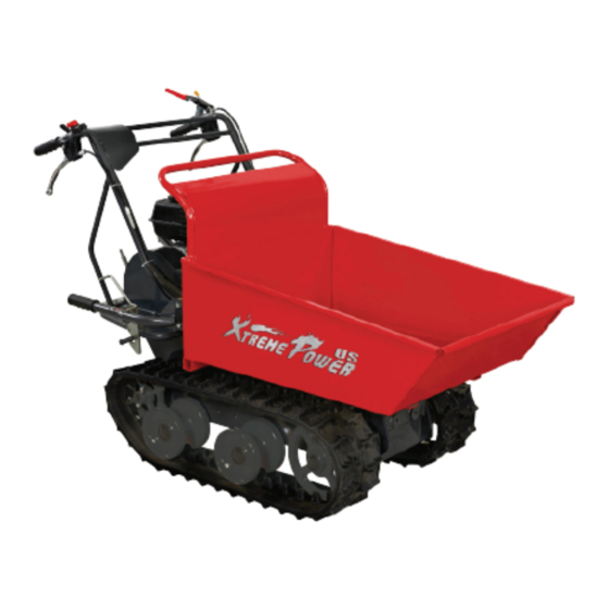
Page 10: Know Your Machine
KNOW YOUR MACHINE Features and Controls Engine Switch Throttle Control Right Steering Lever Clutch Control Lever Left Steering Lever Hopper Tipping Handle Gear Selection Lever Track Gearbox Gas Spring (Optional) MINI TRACKED DUMPER 09715UK00M112_更新回收处理标志_未发排.indd 10 2020/6/29 16:18:40... - Page 11 Recoil Starter Handle Throttle Control Choke Control Fuel Shut-Off Valve Gear Selection Lever engine will not start or run. ON - engine will start and run. The gear selection lever has 4 positions: 3 forward speeds and 1 reverse. To change Recoil Starter Handle speeds, move the speed shift lever to the The recoil starter handle is used to start the...
-
Page 12: Operation
Operation IMPORTANT: DO NOT OVERFILL! This equipment and/or its engine Add Oil To Engine may include evaporative emissions No oil in the engine originally, but c o n t r o l s y s t e m c o m p o n e n t s , a bottle of engine oil is in scope r e q u i r e d t o m e e t E P A a n d / of delivery. - Page 13 CLOSED OPEN The power trackbarrow has a maximum capacity of 660 LBS. However, it is advisable to assess the load and adjust it according to the ground on which the machine will be used. I t i s t h e r e f o r e a d v i s a b l e t o c o v e r s u c h stretches using low gear and taking extra care.
-
Page 14: Maintenance
Adjusting Clutch S u d d e n s t o p p i n g a t a h i g h When the clutch begins to show wear, the speed under a heavy load is not handle reach will become wider, making it recommended. - Page 15 Adjustment Nut Belt Cover M8×20 (×4) Jam Nut Jam Nut Lock Nut Lock Nut Adjustment Nut M6×20 Jam Nut Belt Cover for Gearbox Pulley Lock Nut Loosen the two bolts M8X25 and one bolt 5/16X30 that fix the two belt blockers, no If the above adjustment does not create need to remove them.
- Page 16 Measure the track midline vs. the horizontal Gearbox Lubrication line. The reading must not be more than The gearbox is pre-lubricated and sealed at the 10cm~15cm. factory. Unless there is evidence of leakage or service has been performed on the gearbox, no additional lubricate should be required until 50 hours use.
- Page 17 Loosen the adjusting bolts and pull the Steering Wheel steering wheel axle toward the engine, then track will be loosen. Steering Wheel Steering Wheel Axle Steering Wheel Axle Adjusting Bolt Do not over-tighten your track. The adjustment of the track and the brakes are linked.
-
Page 18: Troubleshooting
Use clean cloths to clean off the outside of STORAGE the machine and to keep the air vents free of obstructions. If the mini tracked dumper will not be used for a period longer than 30 days, follow the steps Do not use strong detergents or below to prepare your unit for storage. -
Page 19: Parts Schedule
PARTS SCHEDULE MINI TRACKED DUMPER 09715UK00M112_更新回收处理标志_未发排.indd 19 2020/6/29 16:19:28... - Page 20 MINI TRACKED DUMPER 09715UK00M112_更新回收处理标志_未发排.indd 20 2020/6/29 16:19:41...
-
Page 21: Parts List
PARTS LIST Description Q'ty Description Q'ty Tensioner Pulley Cable Key 5x35 Safety Control Handle Belt Protect Frame Screw M6x16 Bolt M8x30 Screw M5x20 Fixed Bracket Nut M5 Washer 8 Handle Sleeve Bolt M10x60 Throttle Cable Belt Pulley Throttle Lever Screw M5x12 HOOP Tensioner Pulley ON/OFF Switch... - Page 22 Description Q'ty Description Q'ty Guiding Wheel Circlip 12 Sealing Ring30X42X7 Rivet Assembly Nut M16 Brake Disk Bolt M16x110 Joint Bolt Underframe Weldment Plate Guide Wheel Axle Brake Pull Plate Bolt M10X20 Washer6 Support Bracket Washer6 Flat Gasket 16 Bolt M6x16 Plain Shaft Expansion Brake Cover Pin 4X35...
- Page 23 Description Q'ty Key C5x20 Spline Shaft II Clutch Fork Shaft (R) Gear Box Case ( R) Pin 12x20 Seal FB16x22x4 Output Shaft Bush Gasket Gasket 1 Clutch Spring Spring Guide Bush Clutch Sleeve Spring Gasket Steel Ball 5 Circlip 58 Output Gear Intermediate Joint Bush Intermediate Joint Bush...
- Page 24 Plow Blade (Optional) Parts List Description Q'ty Description Q'ty Bolt M8X35 Bolt M8X50 Shave Plate Active Connecting Weldment Rubber Plate Nut M12 Blade Weldment Bolt M10X25 Washer8 Bolt M8X35 Nut M8 Adjusting Rod Weldment B Landing Leg Weldment Bolt M8X40 Blade Fixed Bracket Weldment Adjusting Rod Weldment A Bolt M8X30...
Need help?
Do you have a question about the 196CC/635HP and is the answer not in the manual?
Questions and answers