Table of Contents
Advertisement
Quick Links
Advertisement
Table of Contents

Summary of Contents for Karl Suss CIC 1200
- Page 1 SUSS Constant Intensity Controller CIC 1200...
-
Page 3: Table Of Contents
CONTENTS Chapter Page Warnings and Safety Hazards Intended Use of the CIC 1200 Electrical Precautions High Pressure Lamps 1.3.1 Electrical Hazards 1.3.2 Lamp Explosion 1.3.2.1 In Case of Lamp Explosion 1.3.3 Exhaust Requirements 1.3.4 Eye and Skin Safety Technical Specifications... - Page 4 Intensity Meter Additional Functions 4.0.1 Full RESET Maintenance and Service Error messages Service Informations 5.2.1 Technical Assistance Contacts - Karl Suss Worldwide List of Figures List of Figures Figur 4.1 Front Panel Figur 4.2 Rear Panel Figur 4.3 Front Panel Figur 4.4...
-
Page 5: Warnings And Safety Hazards
1.1 Intended Use of the CIC 1200 The CIC 1200 is is designed to operate as a smart power supply/ regulator for high pressure UV lamps (see table 2.1) installed in a SUSS lamp house. -
Page 6: Electrical Hazards
1.3.1 Electrical Hazards The voltage and current required to run a high pres- sure lamp constitute a lethal combination. When performing any maintenance on the exposure lamp power supply, lamp housing, or the lamp itself, make sure that the power line to the power supply is disconnected. Proper lamp orientation is crucial. -
Page 7: In Case Of Lamp Explosion
1.3.2.1 In Case of Lamp Explosion If the lamp explodes we recommend the following course of action: Turn power to the supply and machine off immediately. Do not turn off exhaust system. Evacuate the immediate area of the machine to prevent inhalation of the mercury vapor. -
Page 8: Technical Specifications
2 Technical Specifications SUSS CIC 1200 Operating Mode: Single channel constant power. Independent dual channel constant intensity. Remote control Output: LH* 200: 200 W, LH* 350: 750 W, LH* 1000/LH* 1500: 1200 W maximum continuos. 380V DC open circuit. Output regulation: +/- 1% over selected mains input range. -
Page 9: Program Parameters
3 Program Parameters of the CIC 1200 for the various types of exposure lamps. Lamp Type [W Lamp Type [W Lamp Life [h] Lamp Life [h] idle delay 2 2 time 200 Hg 200 Hg 350 Hg 350 Hg 500 HgXe... -
Page 10: Front Panel
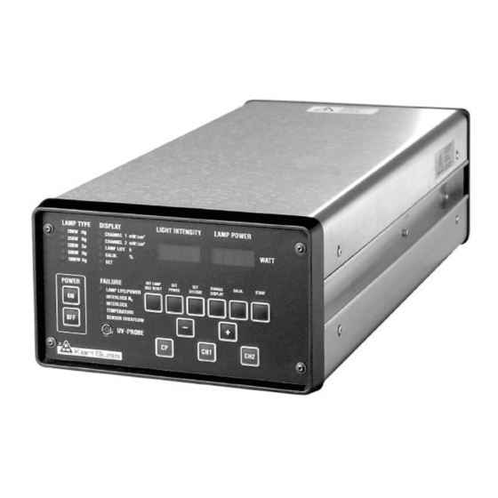
4.1 CIC 1200 Front Panel Figure 4.1 Annunciator Groups (1, 2, 3, 4) 1. Annunciator Group LAMP TYPE 2. Annunciator Group DISPLAY 3. Annunciator Group FAILURE 4. Alphanumeric Display for LIGHT INTENSITY and LAMP POWER 5. Key Pad (see section Key Controls of the CIC 1200) 6. -
Page 11: The Annunciator Group Failure
4.1.1 The Annunciator Group FAILURE LAMP LIFE / POWER LAMP LIFE / POWER The Lamp Life LED will flash indicating that the actual values of voltage, current or power reached the exspected programmed limits. The Lamp Life LED will flash indicating that the lamp has reached its recommended operating life. -
Page 12: Rear Panel
4.2 CIC 1200 Rear Panel Figure 4.2 1. Main Power 5. External Alarm with Fuses (T 10 A) 6. Optical Sensor 2. Remote Start 7. Lamp Interlock 3. RS232 8. Lamp Cooling Interlock 4. Control IN/OUT 9. Type plate... -
Page 15: General Remarks
The alphanumeric display of the front panel reads STAND BY STAND BY The processor of the CIC 1200 is constantly connected to power so it monitors the crucial program steps of the exposure lamp, e. g. the internal clock of the CIC safety programs... -
Page 16: Reset Lamp Hours
SET LAMP LAMP Actuate the key (press button for 2 sec.) to activate the menu LAMP TYPE of the CIC unit. The alphanumeric display shows the currently loaded exposure lamp, e. g. LAMP 1000 LAMP 1000 The corresponding LED of the annunciator group LAMP TYPE is on. Choose the 350 W exposure lamp by actuating the key labeled with Now the LED adjacent to the 350 W is on. -
Page 17: Operating Modes Of The Cic 1200
4.5 Operating Modes of the CIC 1200 4.5 Operating Modes of the CIC 1200 The three operating modes of the CIC are: CP, CH1 and CH2. 4.5.1 Operating mode CP 4.5.1 Operating mode CP CP stands for Constant Power. The exposure lamp is run with constant power. - Page 18 Figure 4.3 Control Panel of the CIC 1200 Key sequence in ignition of the lamp: 1. 1. ON 2. 2. CP 3. 3. START...
-
Page 19: Idle-Mode
4.6.1 Idle The exposure lamp has been ignited and after 5 minutes (depending on the lamp type) has become operational. The alphanumeric display labe- led LAMP POWER shows the message XXXX [W] XXXX To run the lamp in “Idle” mode actuate key IDLE . The display shows IDLE XXX [W] IDLE XXX... -
Page 20: Power Setting
“beep” is heard confirming the operator that the new parameter has been stored. Figure 4.5 Control Panel of the CIC 1200 (Key sequence to set lamp output) 1. 1. Press SET POWER 2. 2. Set value with + Store with 3. -
Page 21: Change Display
4.6.3 Change Display Actuating the key CHANGE DISPLAY (1) one gets access to the follo- wing modes of the annunciator group DISPLAY listed below. The LED of the corresponding mode will be on. To select an item other the one indi- cated press the key CHANGE DISPLAY . -
Page 22: Calibration Modes
4.6.4 Calibration Modes of the Power Supply 4.6.4.1 Basics The calibration of the power supply is done in CP mode. Commence calibration only after the lamp has become operational. Press key CALIB . for 1-2 sec. In the annunciator group DISPLAY the modes The alphanumeric display CHANNEL 1 [mW/cm... -
Page 23: Calibration With The Built In Uv-Meter
4.6.4.2 Calibration Procedure of the CIC with UVP1 or UVP2 NOTE: Always calibrate the control unit in CP mode (constant power mode). Always calibrate the control unit in CP mode (constant power mode). Make sure shutter of the lamp house is open. The key CP of the control panel is illuminated. -
Page 24: Calibration With Ext. Uv-Meter
A high pitched “beep” will be heard and the alphanumeric display shows STORED STORED Thus the average value of the measurements is stored and the CIC returns automatically to the CP mode. Same procedure applies for the other CHANNEL (UVP1) 4.6.4.3 Calibration Procedure with CAL-ext1 or CAL-ext2 Measure intensity of the lamp with the SUSS UV 1000 or any other intensity meter as described in the Operator’s Manual of your machine. -
Page 25: Additional Functions
4.6.4.4 Additional functions of calibration menu Press 5x CALIB 4.6.4.4.1 S1 OK Meaning:Input signal light sensor channel 1 OK Press 6x CALIB 4.6.4.4.2 S2 OK Meaning: Input signal light sensor channel 2 OK The calibration of the digital/analog converter S1OK, S2OK is done by SUSS Service Engineer only! Function: Function:... -
Page 26: Uvpr
Press 7x CALIB 4.6.4.4.3 UVPR Meaning: Input signal of calibrated UV-Probe connected to socket UV-PR PROBE in the front panel will be displayed. Function: Function: The alphanumeric display schows Active modes resp. LED´ s in the annunciatorgroup DISPLAY UVPR UVPR CHANNEL 2 CALIB Press START... -
Page 27: Exit Calibration Menu
NOTE: The maximum output power of the 350 W lamp is 400 [W] NOTE: The minimum output power of the 350 W lamp is 200 [W] Program Parameters of the CIC 1200 for the (see various types of exposure lamps, in table 3.1... - Page 28 A high pitched “beep” will be heard confirming the operator that the parameters have been stored. Now one can run the CIC 1200 in Constant Intensity Mode. Switch subsequently to CHANNEL 1 (CH1) or CHANNEL 2 (CH2) respec- tively (see Section “Change Display”). If the shutter of the lamp house is...
-
Page 29: Calibration Of The Built-In Uv
LIGHT INTENSITY of the CIC 1200. Figure 4.8 Control Panel of the CIC 1200. Control Panel of the CIC 1200. The calibration point (potentiometer) for the built-in UV Intensity Meter is indicated by the arrow. -
Page 30: Additional Functions
4.9 Additional Functions 4.9.1 Full RESET Meaning: Reset all Calibration data Function: Function: The alphanumeric display shows STAN D-BY STAN D-BY Press key - for 3s and max. 1s later START . RES ET? RES ET? CANNEL 1 CALIB Press START RES ET RES ET STAN D-BY”... -
Page 31: Maintenance And Service
NO START START Current error during IGNITION Current error during the first 10s of IGNITION (desired current 5%) CIC 1200 shut down CTRL ERR CTRL Power resp. intensity controller error deviation of desired power resp. intensity is too high for con-... -
Page 32: Service Informations
Should difficulties arise with the use or operation of your Constant Intensity Controller, and you are unable to resolve the problem you can receive further assistance at the Karl Suss office which pro- cessed your order or is currently handling your account. They can give you specific instructions on whom to contact to get additio- nal help or answer any questions. -
Page 34: Contacts - Karl Suss Worldwide
Phone (408) 432-3071 - Fax (408) 432-3072 Germany Germany KARL SUSS KG Präzisionsgeräte für Wissenschaft und Industrie GmbH & Co. KARL SUSS KG Präzisionsgeräte für Wissenschaft und Industrie GmbH & Co. Schleissheimer Strasse 90 - D-85748 Garching b. München - Germany Schleissheimer Strasse 90 - D-85748 Garching b.
Need help?
Do you have a question about the CIC 1200 and is the answer not in the manual?
Questions and answers