
Summary of Contents for Flight Systems anemoi 26005-485
- Page 1 Installation / Operation Manual Version: 1.02 © Copyright 2022 RS Flight Systems GmbH...
-
Page 2: Table Of Contents
Contents Preface ..............................3 Limited Warranty ........................3 Sunburned Display Warranty ....................3 System Description ...........................4 Technical Specifications ........................6 Available Accessories ........................7 Mechanical Installation ........................8 Display Unit..........................8 Sensor Unit ..........................8 Temperature sensor installation .................... 10 P_TOTAL and P_STATIC Connectors ..................10 Drawings Display Unit ......................11 Drawings Sensor Unit ...................... -
Page 3: Preface
This RS Flight Systems product is warranted to be free from defects in materials or workmanship for two years from the date of purchase. Within this period, RS Flight Systems will, at their sole discretion, repair or replace any components that fail in normal use. Such repairs or replacement will be made at no charge to the customer for parts and labor, provided that the customer shall be responsible for any transportation cost. -
Page 4: System Description
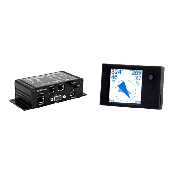
System Description anemoi comprises one sensor and one display unit. Its functionality is as follows: • Precise indication of wind vector, artificial horizon (AHRS) and flight data (TAS, GS, OAT, FL) • Stand-alone system architecture • Sunlight-readable backlit display • Simple and self-explanatory operation (one push button) •... - Page 5 Figure 2-2: Display Unit Figure 2-3: Wiring Harness Kit Figure 2-4: Connection Kit 02.04.2022 | V1.02 Installation / Operation Manual anemoi...
-
Page 6: Technical Specifications
Technical Specifications Sensor Unit Display Unit Dimensions 130 x 55 x 35 mm 44 x 30 x 10 mm (width, height, depth) 5.12 x 2.17 x 1.38 in 1.73 x 1.18 x 0.39 in Mounting Depth 70 mm 25 mm incl. -
Page 7: Available Accessories
Available Accessories Part No. Name Description Live wind indication system for aircraft Kit consists of Sensor Unit and Display Unit anemoi Wind Indication Power supply: 12 VDC 10-757 System Sensor Unit: 130 x 55 x 35 mm Display Unit: 44 x 30 x 10 mm Includes wiring harness 10-752 and connection kit 10-756 Display Unit for anemoi live wind indication system 26005-455... -
Page 8: Mechanical Installation
Mechanical Installation Upon delivery, undertake visual inspection of the package contents for signs of transport damage and verify the information on the type plate sticker against your order. Do not open the device housing. For longer storage of the device, select a dry and clean environment. Make sure that the device is not stored near strong heat sources and that no metal chippings or other dirt can get into the device or its connectors. - Page 9 Menu under “Align DOF”. Three-dimensional CAD-models of the units and the cutout of the display unit are available at the RS Flight Systems website. As waste heat is dissipated via free convection, leave at least a 5 mm gap from the aluminum surfaces to any other object.
-
Page 10: Temperature Sensor Installation
Temperature sensor installation It is recommended to install the temperature probe as closely to outside air temperature (OAT) as practically possible, e. g. inside the nose tip or in the front air vent of the aircraft. Errors in temperature measurement (usually, too warm measurement due to heating from cockpit systems) can have an impact on the airspeed calibration and therefore negatively influence wind anemoi calculation. -
Page 11: Drawings Display Unit
Drawings Display Unit Figure 4-4: Display unit (front view / side view) Figure 4-5: Display unit (rear view) Figure 4-6: Display unit (isometric view) 02.04.2022 | V1.02 Installation / Operation Manual anemoi -11-... -
Page 12: Drawings Sensor Unit
Drawings Sensor Unit Figure 4-7: Sensor unit (isometric view) Figure 4-8: Sensor unit (front view) Figure 4-9: Sensor unit (top view) 02.04.2022 | V1.02 Installation / Operation Manual anemoi -12-... - Page 13 Figure 4-10: Sensor unit (side view) 02.04.2022 | V1.02 Installation / Operation Manual anemoi -13-...
-
Page 14: Electrical Installation
Electrical Installation The sensor unit has six electrical connectors and two pressure connectors on the front side. The front side of the sensor unit is shown in Figure 5-1. Label, type of connector and usage are listed in Table 5-1. Before powering up the unit for the first time, carefully check your wiring. There is one microSD slot to update the firmware, one RJ45 connector to import GPS data from the NMEA output. -
Page 15: Display 1 / Display 2 Connector
Figure 5-1: Sensor Unit Front View Display 1 / Display 2 Connector Displays 1 and 2 use a standard RJ12 connector (6P/6C). Pins 1 and 2 are supplied with +5 VDC, Pins 5 and 6 are ground. The extended pin allocation is shown in Table 5-2. Pin Number Signal Name Function... - Page 16 anemoi The RJ45 connector has the standard IGC pinout, however only the pins Rx ( receives anemoi data) and GND are actively used. does not supply or consume power nor send data (Tx) via the NMEA RJ45 connector. anemoi is operated in parallel with other devices on the RS-232 NMEA bus, a 1:1 Y- Adapter can be used to split the signal.
-
Page 17: Power Connector
POWER Connector The sensor unit uses a standard D-SUB 9 connector. Pin 1 is supplied with +12 VDC, Pin 5 is ground. Pin must be fused with a 1.0 A circuit breaker. The P/N of the circuit breaker is listed in Table 3-2. The anemoi is delivered with a prewired power connector harness, including two power cables and the temperature sensor. -
Page 18: Gps Receiver Connector
GPS Receiver Connector anemoi GPS receiver has a mating connector for the GPS port. The P/N of the receiver is listed in anemoi Table 3-2. The GPS receiver can be used, if no NMEA source is available in the aircraft. Figure 5-5: GPS receiver 02.04.2022 | V1.02 Installation / Operation Manual... -
Page 19: Wiring Diagram
Wiring Diagram 1.0 A anemoi Sensor Unit Main Bus POWER Aircraft GND PWR_IN blue AC_GND Temperature TEMP_PWR yellow Sensor TEMP_DATA black TEMP_GND DISPLAY 1/2 Display Unit PWR_OUT PWR_OUT BUTTON DATA DISPLAY_GND DISPLAY_GND RJ45 Y-Splitter GPS NMEA NMEA_RX NMEA_GND NMEA_GND GNSS Antenna GNSS ANTENNA Figure 5-6: Wiring Diagram 02.04.2022 | V1.02... -
Page 20: Operation
Operation anemoi In this chapter operational procedures for the are described. Startup anemoi starts up as soon as the required supply voltage is provided. The subsequent startup screen is displayed for 2 seconds. The startup page is shown in Figure 6-1. The startup page gives details about the current software version while internal testing routines are performed to ensure correct operation of all electronic components and sensors (TMP, GPS, PRS, IMU). -
Page 21: Wind Page
Figure 6-2: Wind page Figure 6-3: AHRS page Figure 6-4: Data page Wind Page The blue arrow of the wind page symbolizes the current wind vector, and the grey arrow symbolizes the 3-minute average wind vector. The wind page is shown in Figure 6-2 The wind vector is always shown “Heading Up”, meaning that it is aligned with the physical world outside the cockpit. -
Page 22: In-Flight Operation
If the incoming NMEA data provide no GPS (e. g. when the aircraft is in a hangar, or when the NMEA source has not found GPS after boot yet), GS and track are indicated as “- -”. If GPS is available on the ground, correct values for GS and track are displayed. -
Page 23: Setup Menu
Due to physical constraints, the quality and reliability of the indicated wind vector has small variations depending on flight phases. Right after takeoff: Live wind is very reliable, as the takeoff roll has given the inertial measurement platform an ideal opportunity to perfectly align. Normal soaring maneuvering with occasional heading changes (10°... -
Page 24: Calibrate Prs
Calibrate PRS anemoi pitot pressure sensor must be calibrated at least once after installation of the device. Calibration must be done indoors (e. g. hangar). To compensate for any long-term drift of the differential pressure sensor, a new calibration should be done if the TAS indication exceeds 20 km/h on ground in calm wind Note that at low airspeed (i. -
Page 25: Align Dof
After choosing a duration (Figure 6-8) and confirming (Figure 6-9), AHRS will be locked for the chosen amount of time. Note that GPS signal is required to lock the AHRS, as time and date information is transferred via NMEA. If no GPS signal is available, the system will not be locked, and an error message will be displayed. -
Page 26: Errors
Errors Sensor error anemoi As soon as an error in any of the four sensors (GPS, IMU, PRS, TMP) appears, switches to the startup screen. The malfunctioning sensor is highlighted with a red color. In Figure 6-12 there is an exemplary GPS error displayed which occurred due to a lack of satellite signal reception. -
Page 27: Firmware / Software Update
Make sure to format the microSD card in FAT32 format (exFAT/NTFS is not supported!) • Ensure the microSD card is empty • Download the latest firmware from following RS Flight Systems website • Do not rename the firmware file Flashing mechanism sensor unit: •... -
Page 28: Abbreviations And Terms
Abbreviations and Terms Abbreviation Description Active Aircraft Voltage AHRS Attitude Heading Reference System Direction of Flight Flight Level GNSS / GPS Global Navigation Satellite System (e. g. GPS, Galileo, GLONASS) Ground Speed Heading Inertial Measurement Unit Liquid Crystal Display NMEA National Marine Electronics Association Pressure Outer Air Temperature... - Page 30 RS Flight Systems GmbH Oberer Luessbach 29-31 82335 Berg | Germany anemoi@rs-flightsystems.com www.rs-flightsystems.com anemoi | Version: 1.02 © Copyright 2022 RS Flight Systems GmbH...
Need help?
Do you have a question about the anemoi 26005-485 and is the answer not in the manual?
Questions and answers