
Summary of Contents for ANLIDAR MYTORQ MY-SAVER
- Page 1 MY-SAVER User Manual Model : MY-SAVER ANLIDAR INDUSTRIAL CO., LTD. http://www.anlidar.com Y2F214-2E-010 20200312...
-
Page 2: Table Of Contents
Table of Contents Product specification introduction ....................2 Appearance introduction ....................3 Panel ..........................3 Bottom ..........................4 Upper case ........................4 LCM display function introduction ................... 5 System setting method introduction ................5 Hot key function introduction ..................5 Enter setting function page ..................... -
Page 3: Product Specification Introduction
1. Product specification introduction Model MY-SAVER Input Voltage AC 110V / 240V Input Frequency 50 - 60Hz Input Current 6.3A Input Voltage DC 40V Output Current Max 9A Output Power 360W Function Period 1s ON / 3s OFF Size 185 x 241.4 x 146.8(mm) Weight 3.7Kg DC screwdriver model:... -
Page 4: Appearance Introduction
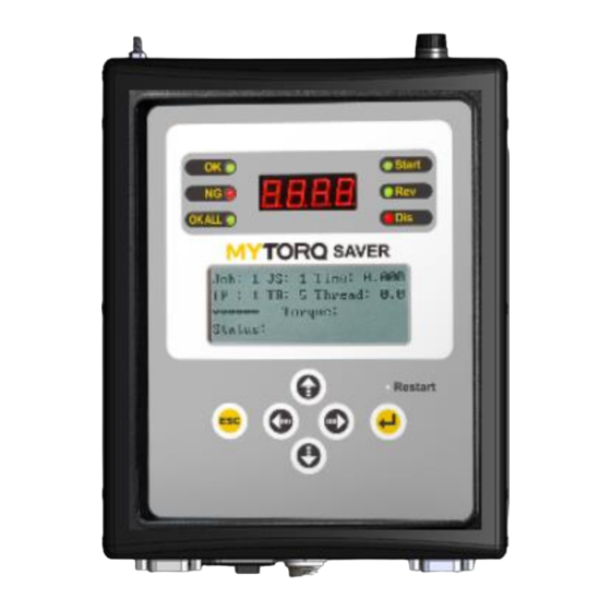
2. Appearance introduction 2.1 Panel 1. OK signal LED 7. Start signal LED 2. NG signal LED 8. Reverse signal LED 3. OKALL signal LED 9. Disable signal LED 4. Four-digit-seven-segment display for 10. 16X4 LCM display setting function torque value 5. -
Page 5: Bottom
2.2 Bottom Tool connector Software update port External wireless module port Wired communication port Barcode scanner USB type-A port Protocol output port Micro SD card slot (Data Storage) 10. Output signal port Socket and switch Input control signal port Voltage Choice Switch 2.3 Upper case 1.DC fuse station (Content 10A/250V) 2.Grounding station (FG) -
Page 6: Lcm Display Function Introduction
2.4 LCM display function introduction 1. Display job 2. Display sequence 3. Display system status Job: 1 JS: 1 Time:0.267 4. Display job sequence 5. Display repeat times TP: 1 TR: 5 Thread:1.5 6. Display action time 7. Display number of turns ****** Torque:11.27kgc 8. -
Page 7: Control Setting
4. Control setting Name Set Up Time Function Description Default and Value setting OPERTION MODE STD/ADV Connection mode. STD: Standalone mode. ADV: KL-AMS network system. (STD/ADV) connection mode. DEVICE ID 001~250 Equipment No. TOOL START Both/Push Choose tool start mode. Both METHOD /Lever... -
Page 8: Program Setting
BARCODE Define a valid Below steps will show you how to use certain Job:01 SETTING barcode range section of a barcode to select/switch Job. From:01 How to select/switch Step 1. Determine the initial point of the From:01~54 Bits:01 Job by barcode section (01-20) Bits:01~54 scanning... -
Page 9: Screw Setting
6. Screw setting Name Set Up Value Function Description Default setting Screw Sequence 01~99 Setup screw parameter. Screw Name ****** Setup screw parameter name. It can choose ****** number、capitals and lower case letters、number. Screw Reverse 001~250 Setup screw reverse strategy Sequence 1 001~250 Setup 1... -
Page 10: Confirm Mode
8. CONFIRM mode Code Description Disable method External GATE Signal Once external confirmation “GATE” Trigger once External GATE Signal Twice external confirmation “GATE” Trigger twice When『OKALL disable screwdriver』function is on, LCM Panel Enter button/ will display『C3』after a batch completed. External CONFIRM External GATE Signal When 『OKALL disable screwdriver』... -
Page 11: External Output Control Function Description
GATE function abnormal:When the GATE function is on and Please confirm GATE function abnormal, the buzzer will alarm and LCM displays phase and setting mode this Er. Screwdriver end communication error:When the electric screwdriver communication error occurs, the electric screwdriver will be stopped and the LCM displays this ES. Calibration is required when EOC is stated on LCM display. -
Page 12: External Input Control Function Description
10. External input control function description Connector No Symbol Definition Function Description External start 1. When CN1+CN2 short (CLOSE), screwdriver CN 1 signal input start functioning. START_IN 2. When CN1+CN2 open (OPEN),screwdriver stop CN 2 functioning. 1.When external reverse signal CN3+CN4 short External reverses (CLOSE) first and activate signal CN1+CN2 short (CLOSE), CN 3... -
Page 13: Data Transmission Description And Flow Control Suggestion
11. MY-SAVER Data transmission description and flow control suggestion VER:2020060201 1. Controller power on and time synchronization After controller is power on, it will send data {REQ100...} each second to inform external device such as computer、PLC、AMS. The external device needs to reply {CMD100,..} that to sync the external device time to the controller. - Page 14 Cyclic communication Ethernet Controller send to external device External device Controller REQ100(send/sec.) PC/AMS/PLC MY-SAVER External device response to controller (Slave) (Master) CMD100(send/sec.) Get Barcode Data External device Controller Barcode data from the controller REQ101 PC/AMS/PLC MY-SAVER External device response to controller (Slave) (Master) CMD100...
-
Page 15: Exploded View Drawing & Parts List
MY-SAVER Basic Data Output Protocol Description (Ver1.0_20200519_01) COMPORT Setting:Baud rate : 115200/9600(CTDS 1.7X), Data bit : 8 , Stop bit : 1, Parity bit :NON Serial communication Mode -ASCII (American Standard Code for Information Interchange) There are three basic data output formats send from device (MY-SAVER) to external system (DAS/AMS/Other System) via the buildin RS232 port on the device : 1.Command {REQ100} : Send from Device to Host (Send device status to host per second after device startup ready) 2.Command {REQ101} : Send from Device to Host (Send barcode data to host immediately after barcode scaned a data) 3.Command {DATA100} : Send from Device to Host (Send last shutoff data to host immediately and repeat per second after screwdriver shutoff ) - Page 16 15 Job 01~50 String 2 Byte 99-100 Selected Job 16 Sequence 01~50 String 2 Byte 102-103 Selected Sequence 17 Program unit 01~99 String 2 Byte 105-106 Selected Unit Program Setup program name, it can choose number、 18 Program Name 1~6 Bytes String 6 Byte 108-113...
Need help?
Do you have a question about the MYTORQ MY-SAVER and is the answer not in the manual?
Questions and answers