Table of Contents
Advertisement
Quick Links
Advertisement
Table of Contents

Related Manuals for Intermatic eco CI7


Summary of Contents for Intermatic eco CI7
- Page 1 Operating manual eco CI7 and CG7...
- Page 2 This manual ensures safe and efficient use of the “eco CI7” and “eco CG7” timers (referred to as “device” in the following). This manual is a component of the devices and must remain accessible at all times for everyone who uses the devices.
- Page 3 – including excerpts – and use and/or disclosure of the content without the written permission of Intermatic (referred to as “manufacturer” in the following), except for internal purposes, is not permitted. Violations will result in liability for compensation. The manufacturer reserves the right to assert additional claims.
- Page 4 The copyright is held by the manufacturer. ©Intermatic Incorporated 1950 Innovation Way, Suite 300 Libertyville, IL 60048 Declaration of conformity and download instructions The declaration of conformity for the devices described in this manual, a download of the manual, and the technical www.
-
Page 5: Table Of Contents
Overview..........7 Safety........... 19 Installation..........22 Configuration........45 Menu structure........... 45 Setting the time and date......52 Programming........56 Selecting the predefined programmes..56 Changing the predefined programmes..59 Creating an individual switching program... 70... - Page 6 Deleting a programme........ 72 Selecting summer/winter time....75 Selecting the operating mode..... 77 Disposal..........79...
-
Page 7: Overview
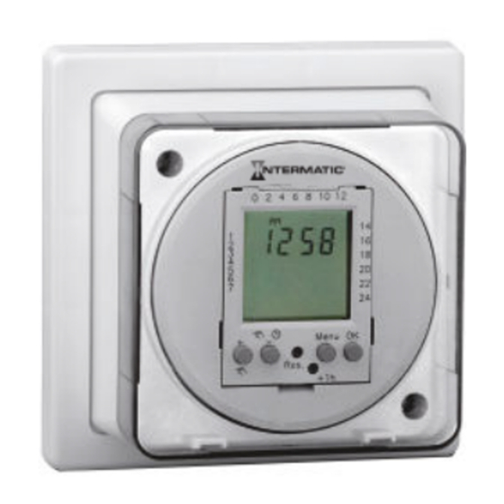
Overview Fig. 1: Insert Display of day blocks/days Display of on/off times Display of the current time... - Page 8 Fig. 2: Rear view of “eco CI7” Mounting holes Flexible union fittings for cable feed-through...
- Page 9 Display Function Set the time format (24 h or 12 h) Set summer or winter time On/off time memory space Switch between automatic mode, perma- nently on, permanently off Automatic mode Prog. Switching programme is displayed Lights up in automatic mode via when permanently ON via...
- Page 10 Button Function Press briefly to increase value by 1 Press and hold to increase value by 5 Only in operating mode: Switch between automatic mode, perma- nently on, permanently off − Press briefly to reduce value by 1 Press and hold to reduce value by 5 Menu Start/exit programming mode;...
- Page 11 Button Function Res. Reset device to factory settings +1 h Switch between summer and winter time...
- Page 12 Description of function The “eco CI7” and “eco CG7” timers are digital single- channel synchronous timers that switch connected loads on and off at defined times. The times are either set by means of a predefined switching programme or in an individually defined switching pro-gramme.
- Page 13 On delivery, three profiles – P01, P02 and P03 – are pre- defined on the device, each with different switching times. The times of these profiles can be copied, adjusted and/or amended. All three profiles apply to all seven days of the week. The following profiles are prede- fined:...
- Page 14 Fig. 3: Predefined profiles P01, P02, P03 P01 07:00 – 20:00 (Mon – Sun) P02 07:00 – 12:00 and 14:00 – 20:00 (Mon – Sun) P03 07:00 – 12:00, 14:00 – 18:00 and 20:00 – 22:00 (Mon – Sun)
- Page 15 In addition, you can use the P-- individually program- mable switching programme. Here, you define all the times individually. Each changed or individual time is assigned to the seven days of the week in the form of day blocks or individual days:...
- Page 16 Day blocks or days Mon – Mon – Mon – Sat – Indiv. days Tue 2 Thu 4 Fri 5...
- Page 17 Mon – Mon – Mon – Sat – Indiv. days Sat 6 Sun 7 Contents The following components are included in the contents: Number Designation “eco CI7” or “eco CG7” Screws...
- Page 18 Number Designation Strain relief clamps Wire end sleeves...
-
Page 19: Safety
16 A. The connected devices must comply with the limits specified in the technical data. The “eco CI7” and “eco CG7” timers may only be used in private and commercial areas at ambient temperatures from -10 °C to +55 °C. - Page 20 Residual risks WARNING! Danger to life due to electric shock! Improper assembly and installation of the device may result in life-threatening electrical voltages. − Have assembly and connection performed by a qualified electrician only.
- Page 21 WARNING! Danger due to insufficient wire cross-sec- tion! If wires with an insufficiently large cross-sec- tion are used, short circuits or fires may occur. − Only use terminals with a cross-section between 0.5 mm² and 2.5 mm² for flex- ible wires.
-
Page 22: Installation
Installation The “eco CI7” is mounted on the wall. The “eco CG7” is installed on a mounting socket (BS 4662 or BS 5733). In general, the following instructions apply to both models. Where there are differences, the corresponding model number is specified... - Page 23 NOTICE! Danger of material damage to wires in the wall! Selecting the wrong installation position can result in material damage to any wires in the wall. − Make sure that there are no wires in the wall at the installation position. Personnel: •...
- Page 24 • Drill • Phillips screwdriver • Crimping pliers for wire end sleeves • Cutting tool Materials: • Wire end sleeves (4 pieces) • Strain relief clamps (2 pieces) • Screws (2 pieces)
- Page 25 Installing the housing base Fig. 4: Installing eco CG7 on a mounting socket (Fig. 4/1)
- Page 26 Screws For “eco CI7”: Remove the plastic cover. For “eco CG7”: Remove the plastic cover (Fig. 4/5). For “eco CI7”: Undo the screws on the housing cover. For “eco CG7”: Undo the screws (Fig. 4/6) on the housing cover (Fig. 4/4) using a Phillips screwdriver.
- Page 27 The dial is connected to the housing base by blue connection wires. NOTICE! Danger of material damage! When the dial is lifted up, the connection wires may be damaged. − Lift up the dial carefully. − Do not remove the dial from the housing base.
- Page 28 For “eco CG7”: Remove the housing cover (Fig. 4/4) and the dial together with the con-nected housing base (Fig. 4/3). For “eco CI7”: Fasten the housing base to the wall. For “eco CG7”: Install the housing base (Fig. 4/2) on the mounting socket (Fig. 4/1).
- Page 29 11. Crimp the wire end sleeves using the crimping pliers. Electric connections To ensure that the wiring is correct, consult the operating manual for the heating system in use. The devices have protection class 1, so earthing is essential. Connect the earth cor- rectly.
- Page 30 Fig. 5: Housing base CG7 12. Insert the earth connection wire into the earth con- tact (Fig. 5/2).
- Page 31 Fig. 6: Housing base CI7 13. Insert the earth connection wire into the earth con- tact (Fig. 6/1).
- Page 32 14. For “eco CG7”: Thread the connection wires into the device through the cable feed-through (Fig. 5/1).
- Page 33 Mains connection CG7 Fig. 7: Mains connection CG7...
- Page 34 15. For mains connection CG7: Insert the connection wires into the corresponding terminals in accord- ance with the relevant wiring diagram (Fig. 7) (N = neutral conductor; L = live conductor) (Fig. 7).
- Page 35 Voltage-free connection CG7 Fig. 8: Voltage-free connection CG7...
- Page 36 16. For voltage-free connection CG7: Insert the connec- tion wires into the corresponding terminals in accordance with the relevant wiring diagram (Fig. 8) (N = neutral conductor; L = live conductor) (Fig. 8).
- Page 37 Mains connection CI7 Fig. 9: Mains connection CI7...
- Page 38 17. For mains connection CI7: Insert the connection wires into the corresponding terminals in accord- ance with the relevant wiring diagram (Fig. 9) (N = neutral conductor; L = live conductor) (Fig. 9).
- Page 39 Voltage-free connection CI7 Fig. 10: Voltage-free connection CI7...
- Page 40 18. For voltage-free connection CI7: Insert the connec- tion wires into the corresponding terminals in accordance with the relevant wiring diagram (Fig. 10) (N = neutral conductor; L = live conductor) (Fig. 10). NOTICE! Tightening torques To avoid damage and faulty contacts, tighten the terminals using a torque of 0.75 Nm.
- Page 41 Fig. 11: Installing the strain relief clamps 20. For “eco CI7”: Screw on the strain relief clamps (Fig. 11/1) using the screws provided (Fig. 11/2).
- Page 42 The housing has two flexible union fittings for the cable feed-through, each with three different possible sizes for different diameters of connection wire. For “eco CI7”: Use a cutting tool to cut the flexible union fittings to the correct size for the connection wires.
- Page 43 This results in material damage to the wires and faulty contacts. − Make sure that the wires are not pinched when the you close the housing. 22. For “eco CI7”: Screw the housing cover onto the housing base using a Phillips screwdriver.
- Page 44 23. For “eco CG7”: Screw the dial (Fig. 4/3) and housing cover (Fig. 4/4) onto the housing base (Fig. 4/2) using a flat-head screwdriver. 24. For “eco CI7”: Replace the plastic cover. 25. For “eco CG7”: Replace the plastic cover (Fig. 4/5).
-
Page 45: Configuration
Configuration Menu structure Initial installation Read/setting (menu) (reset) 24 h flashes. [ +/− ] to set the time format (24 h or AM), then Press [OK] . confirm with... - Page 46 Initial installation Read/setting (menu) (reset) The hour flashes. [ +/− ] to set the hours, then confirm with [OK] . Press The minute flashes. [ +/− ] to set the minutes, then confirm with Press [OK] . Monday (1) flashes. [ +/−...
- Page 47 Initial installation Read/setting (menu) (reset) Setting the programme: P01, P02, P03, P-- [ +/− ] to set the Press on/off times, then confirm [OK] or end program- with [Menu] . ming with...
- Page 48 Initial installation Read/setting (menu) (reset) Setting the switching Setting the switching times: times: First free memory space First free memory space flashes. flashes. [-] to go back one [OK] to confirm the Press Press memory space or press settings. [OK] to confirm the set- ting.
- Page 49 Initial installation Read/setting (menu) (reset) Setting the switch-on time: The hour flashes. [ +/− ] to set the hours, then confirm with [OK] . Press Setting the switch-on time: The minute flashes. [ +/− ] to set the minutes, then confirm with Press [OK] .
- Page 50 Initial installation Read/setting (menu) (reset) Setting the switch-on time: Days flash. [ +/− ] to set the day (Mon 1 to Sun 7), then con- Press [OK] . firm with Setting the switch-off time: The hour flashes. [ +/− ] to set the hours, then confirm with [OK] . Press...
- Page 51 Initial installation Read/setting (menu) (reset) Setting the switch-off time: The minute flashes. [ +/− ] to set the minutes, then confirm with [OK] Press [Menu] to end programming. and press A maximum of 20 memory spaces can be assigned: 10 switch-on times and 10 switch-off times Menu...
-
Page 52: Setting The Time And Date
Initial installation Read/setting (menu) (reset) Operation Setting the time and date For the device to use the defined switching times cor- rectly and to control the connected loads at the correct time of day, the time and date have to be set before ope- ration. - Page 53 Selecting the time format Fig. 12: Selecting the time format...
- Page 54 Setting the hours and minutes Fig. 13: Setting the hours and minutes...
- Page 55 Setting the day of the week Fig. 14: Setting the day of the week Monday Friday Tuesday Saturday Wednesday Sunday Thursday...
-
Page 56: Programming
Programming Selecting the predefined programmes Fig. 15: Predefined profiles P01, P02, P03... - Page 57 P01 07:00 – 20:00 (Mon – Sun) P02 07:00 – 12:00 and 14:00 – 20:00 (Mon – Sun) P03 07:00 – 12:00, 14:00 – 18:00 and 20:00 – 22:00 (Mon – Sun) In addition, you can use the P-- individually program- mable switching programme.
- Page 58 Fig. 16: Selecting the predefined programmes...
-
Page 59: Changing The Predefined Programmes
Changing the predefined programmes Fig. 17: Selecting the programme... - Page 60 Fig. 18: Changing fixed programmes...
- Page 61 Effects of the buttons (Fig. 18) [–] Programming the predefined programs: (e.g. the memory spaces Prog01 – Prog04 for P02) [OK] Programming the next free memory space, e.g.: • Sat – Sun 22:30 (p.m.) ON (Prog05) • 23:00 (p.m.) OFF (Prog06) [Menu] Ending programming...
- Page 62 Setting the time Fig. 19: Setting the time...
- Page 63 [−] to return to the previous or the pre- Press defined memory spaces. [OK] to jump to the next free memory Press space. indicates that the memory space is an ON time. indicates that the memory space is an OFF time.
- Page 64 Fig. 20: Setting the day blocks or days...
- Page 65 Day blocks or days Mon – Mon – Mon – Sat – Indiv. days Tue 2 Thu 4 Fri 5...
- Page 66 Mon – Mon – Mon – Sat – Indiv. days Sat 6 Sun 7...
- Page 67 Shifting the time Fig. 21: Shifting the time...
- Page 68 If you want the connected load to switch off the next day, you can shift the off time by 24 hours. [−] and [OK] to enter the next − CI7: Press [−] and [Menu] to exit the time, or press mode.
- Page 69 To make further changes or add new times, repeat the steps as shown in Ä Chapter " Creating an individual switching program" on page 70. Other- [Menu] . wise exit the mode by pressing If the device is in an ON period when you finish set- [+] multiple times until auto- ting the times, press matic mode is activated.
-
Page 70: Creating An Individual Switching Program
Creating an individual switching program Fig. 23: Creating an individual switching program... - Page 71 Fig. 24: Creating an individual switching program After the last step, set the hours, minutes and day of the week (Ä Chapter "Setting the time and date" [OK] . on page 52) and confirm with...
-
Page 72: Deleting A Programme
Deleting a programme Times are saved as pairs (on time and off time). If you want to delete a time period, you only have to delete the ON time manually – the corresponding OFF time is deleted automati- cally. - Page 73 Fig. 25: Selecting the programme...
- Page 74 Fig. 26: Deleting time periods...
-
Page 75: Selecting Summer/Winter Time
Selecting summer/winter time Personnel: • User Prerequisite: • The time has been set. [ +1 h] to switch between summer and Press winter time. - Page 76 Fig. 27: Selecting summer/winter time [ +1 h] to add an hour to the current time Press (summer time). +1 h appears on the display. ð...
-
Page 77: Selecting The Operating Mode
[ +1 h] again to subtract an hour from the cur- Press rent time (winter time). +1 h disappears from the display. ð Selecting the operating mode In addition to automatic mode, which switches according to the defined switching times, the device can also be switched permanently on or off. - Page 78 Display Mode Automatic mode Permanently on Permanently off...
-
Page 79: Disposal
Disposal ENVIRONMENT! Environmental hazard! Incorrect disposal could result in environ- mental dangers. − Electric scrap and electronic components must be disposed of correctly, i.e. the parts for disposal must be sorted into material groups. - Page 80 − Batteries/rechargeable batteries (Directive 2006/66/EC) and electrical or electronic scrap must under no circumstances be disposed of with general waste. If in doubt, please obtain information about environmentally responsible disposal from specialist disposal companies. − Disposal must be environmentally respon- sible and must employ state-of-the-art environmental protection, recycling and disposal technology.
- Page 84 Intermatic Incorporated 1950 Innovation Way, Suite 300 Libertyville, IL 60048 Telephone: +1 815 675 7000 www.intermatic.com 156--02320 05/21/V01...
Need help?
Do you have a question about the eco CI7 and is the answer not in the manual?
Questions and answers